5.24
BODY / STEERING / SUSPENSION
9923523 - 2012
RANGER
RZR 570 Service Manual
© Copyright 2011 Polaris Sales Inc.
REAR A-ARMS
Removal
The following procedure details upper and lower A-arm
removal an d r eplacement on one side of th e veh icle.
Repeat the following steps to remove the A-arm(s) from
the opposite side.
NOTE: Use the exp loded v iew in t his se ction as a
reference during the procedure.
1. Elevate and safely support the rear of the vehicle off
the ground.
2. Remove the wheel nuts, and rear wheel.
Upper A-arm Removal
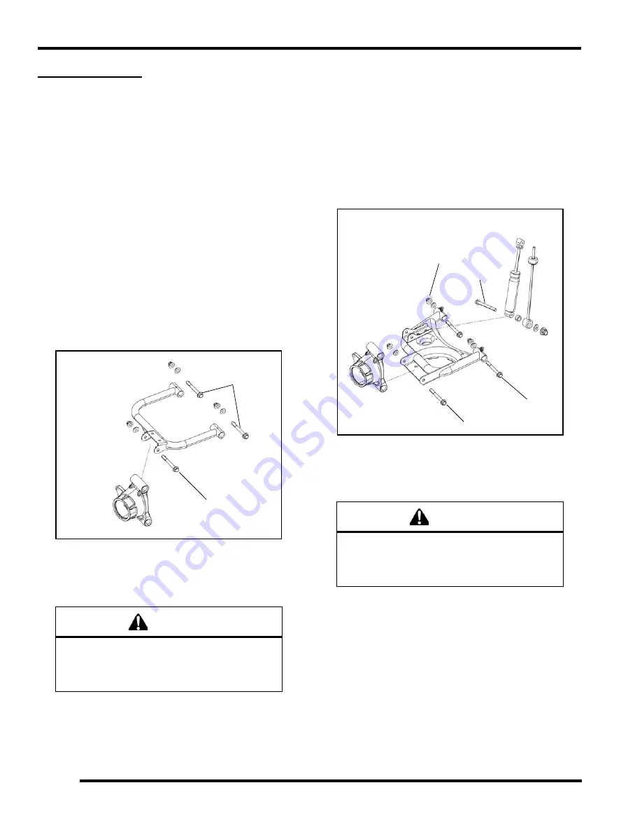
1. Remove the fastene r (A) attaching the u pper A-arm
to the bearing carrier.
2. Remove the (2) fastener (B) attaching the upper A-
arm to the frame and remove the upper A-arm from
the vehicle.
3. Examine bushings and pivot tubes. Replace if worn.
Discard hardware.
4. If not replacing the A-arm, thoroughly clean the a-arm
and pivot tubes.
5. Insert new A-arm bushings and pivot tubes into new
A-arm.
Lower A-arm Removal
1. Disengage the rear brake line from the routing clip on
the lower A-arm.
2. Remove the fastener (C) retaining the lower portion of
the shock and stabilizer linkage to the lower A-arm.
3. Remove the fastener (D) attaching the lower A-arm to
the bearing carrier.
4. Remove the (2) fasteners (E) attaching the lower A-
arm to the frame and remove the lower A-arm from the
vehicle (see previous illustration).
5. Examine bushin gs an d p ivot tub es (se e “Explo ded
View”). Replace if worn. Discard hardware.
6. If not replacing the A-arm, thoroughly clean the A-arm
and pivot tubes.
7. Insert new A-arm bushings and pivot tubes into new
A-arm.
WARNING
The locking agent on the existing bolts was
destroyed during removal. DO NOT reuse old
hardware. Serious injury or death could result if
fasteners come loose during operation.
A
B
WARNING
The locking agent on the existing bolts was
destroyed during removal. DO NOT reuse old
hardware. Serious injury or death could result if
fasteners come loose during operation.
C
D
E
E
Summary of Contents for 2012 RANGER RZR 570
Page 4: ......


