background image


RespiraSense


Instructions For Use  


RespiraSense


PDS-801-007 Revision 2  


Page 

67

 of 

77


S

ECTION 

10


A

SSOCIATED 

IT


E

QUIPMENT


The following section provides information about the associated IT equipment of the RR Monitor. 

Note 

The mobile medical software application is installed onto the hand-held device by 
the manufacturer. 


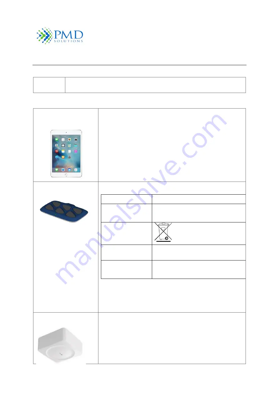
Table 18 List of Associated IT Equipment 

iPad Mini 4 or 7

th

 Gen or 

above 
PDS-701-000 


Approved Mobile device for RS Device Mobile Medical Applications 

Multi Charging Dock  
PDS-102-000


Charging Dock for RS Devices 
 

Power Supply 

25 W   5 VDC / 5 A 

Output 

0.5A / 5V x 6 ports 

4A / 5V x 1 port (USB) 

WEEE 


CE 

Power Supply and charging station are CE 
marked 

Power source 

Mains-Powered 

90-264VAC~50/60Hz 1A MAX 


The charger is to be used outside of the patient 
environment. 


The charger is to be commissioned by IT professionals. 


The charger should be operated by trained personnel. 

Air Repeater Module 
PDS-901-000 


WiFi to Bluetooth repeater for enabling RS Device Air Dashboard


Summary of Contents for RespiraSense RS Device

Page 1: ...ect operation of the RespiraSense Device General knowledge of respiratory rate patient vital monitoring and qualifications in healthcare are prerequisites for correct use of the RespiraSense Device by...

Page 2: ...thout receiving training in its use from an authorised trainer The RS Device must only be installed and put into service in accordance with the information provided in this documentation and reference...

Page 3: ...Emitting Diode Lobe The electronic component of the RS Device MAC Medicare Administrative Contractor MRN Medical Record Number QR code Square matrix type barcode for product identification RespiraSens...

Page 4: ...inicians should assess additional physiological parameters or run additional tests before making a diagnosis and prescribing treatment The RS Device can be used in the home environment as instructed b...

Page 5: ...authorised distributor if in doubt of any component Do not use RS Device on patients who are acutely ill or clinically unstable in the home healthcare environment Use in this way will lead to failure...

Page 6: ...e the RS Device or any associated IT equipment where the controls or settings can be changed by the patient unless required to e g self care in community Do not place the RS Device on high powered ele...

Page 7: ...able defines the symbols that are found on the packaging and labelling of the Device Symbol Caution Symbol Description NAME AND ADDRESS OF LEGAL MANUFACTURER DATE OF MANUFACTURE LOT OR BATCH NUMBER DO...

Page 8: ...tructions For Use RespiraSense PDS 801 007 Revision 2 Page 7 of 77 Electronic instructions for use available on the software application Consult Instructions for Use Direct Current DC Input output Cau...

Page 9: ...on 12 Product Description 14 Position of Users 14 Features and Benefits 14 Indications for Use 14 Principles of Operation 15 Respiratory Rate 15 Monitoring during Motion 16 Declaration of Essential Pe...

Page 10: ...tory Rate Thresholds during Monitoring 39 Step 9 Alter LED and Sounder Settings 39 Step 10 Removal Disposal and Recharging 40 Using the RS Device in the Home Healthcare Setting 41 Limitations of Respi...

Page 11: ...ding Respiratory Rate Data from Lobe 54 Alarm Scenario and Red LED 56 Section 7 Product Specification 58 Physical 58 Environmental 58 Battery 58 Sounder 58 Compliance 59 Respiratory Rate Measurement L...

Page 12: ...IT Equipment 67 Section 11 Associated Mobile Medical Applications 69 Description of the RS App Air Mode 69 Air Dashboard 69 Section 12 Warranty and Agreements 72 PMD Solutions Limited Warranty 72 Sale...

Page 13: ...pecial care needs to be exercised by the patient or operator to avoid patient injury or damage to the product Note Provided when additional general information is required Respiratory Rate Monitor Ove...

Page 14: ...a tablet computer onto which the Associated Mobile Medical Applications are installed and operated The main Associated Mobile Medical Applications are show in Table 2 These Instructions for Use will...

Page 15: ...e This is supplied on a portable hand held device that allows easy data retrieval and display The RS App is compatible with mobile computers that comply with EN IEC 60950 1 and have the appropriate so...

Page 16: ...in the assessment of the health status of a patient Respiratory rates can change with fever illness or other medical conditions For ventilation to occur some sort of mechanical displacement of the th...

Page 17: ...racy during patient movement In cases of extreme or prolonged motion the RS Monitor will refrain from providing a RR data point if the result is determined to be of insufficient certainty Declaration...

Page 18: ...he main features of the RespiraSense Device and associated mobile medical applications available Detailed instructions on the use of the RS APP are found in Section 3 Patient Monitoring 1 RespiraSense...

Page 19: ...ck Referenc e Name Description 1 Lobe charging slot The resting place of the Lobe during charging and storage 2 Power indicator Green LED to indicate power is supplied to the Charger 3 Micro suction P...

Page 20: ...splays a list of all nearby RS Devices which are monitoring patients A summary of up to four RS Devices are shown with more available using a scroll interface when required The device list can then be...

Page 21: ...patient Device Count Indicates number of devices detected Allows the operator to associate a Lobe with the Medical Record Number MRN or another identifying name of a patient See Section 3 Patient Mon...

Page 22: ...t Displays SpO2 measurement of patient 7 Alarm Thresholds Upper and Lower Alarm Thresholds Set for patient In the event of an alarm scenario the Patient Information Panel will flash Red In Bluetooth m...

Page 23: ...xpand Graphs Allows user to expand graph to full screen display 5 Suspend Button Allows operator to suspend measurement for 3 minutes before it disappears from the dashboard and app 6 RR measurement t...

Page 24: ...Function Screen displays the Threshold Alteration Interface shown in Figure 8 This interface allows the user to change respiratory rate alarm thresholds Details on how to use this menu is provided in...

Page 25: ...user to specify averaging window length 6 OK Button Prompts user to save new thresholds 7 Cancel Button Returns user to previous screen without changing thresholds 8 Sounder Setting Displays sounder s...

Page 26: ...Settings when adding a patient or back to the Respiratory Rate Measurement Function Screen if accessory is being added to existing patient 4 Confirm Confirms the added accessory to be measured Alarm...

Page 27: ...e operator should replace the patient worn Lobe with another fully charged Lobe and follow the appropriate setup and operation procedures Checking Battery Levels Always ensure that the Lobe and the ha...

Page 28: ...oard 15 shows this screen All available nearby devices will be displayed as they are discovered The user can then select the correct device from the list by referencing the serial number on the back o...

Page 29: ...Allows user to cancel current process Rename Confirmation Screen Before completion of the renaming process a confirmation screen is displayed This is studied by the practitioner to ensure the device i...

Page 30: ...imits will trigger an alarm 4 RR Averaging Window Displays the currently configured RR Averaging Window 5 Confirmation Buttons Allows user to proceed with registration 6 Cancel Button Allows user to c...

Page 31: ...lt settings RS App Icons Table 13 lists the icons used in the RS App Table 83 RS App Icons Icon Name Description Help Icon Brings user to RS App Help Menu which includes the IFU Back Icon Returns user...

Page 32: ...d Displayed on Dashboard when the Sensor signal is not detected by the Lobe Lobe Settings Alert Displayed on the Dashboard when any Lobe settings have been changed from default Alarm Paused Icon Displ...

Page 33: ...s The RS App will only scan or accept keyboard input from characters in the ASCII set Non ASCII characters will be rejected and a warning displayed The ASCII set consists of the following characters A...

Page 34: ...R Monitor derives its readings See Section 1 Overview for more information Be familiar with the controls and operation of the RS Device Understand the alarms and status indicators of the RS Device See...

Page 35: ...e s battery dies once the patient MRN name is identical the patient s information will be transferred to the new lobe and be seen on the RS app 5 Verify that alarm limits Lobe identifier averaging win...

Page 36: ...when the RS Device is attached Once attached the RS Device can be repositioned to facilitate removal and reapplication between washing showering and tests WARNING Do not use RS Device on any patient...

Page 37: ...n Find bottom rib using index four finger Place Sensor upper Finger below finger and in line with rib Find bottom rib with index finger and place Sensor upper leg on top of finger Figure 18 Summary of...

Page 38: ...on Patient ID b MRN Available Select the Camera icon on the Dashboard and scan the MRN barcode of the patient using the camera interface provided c MRN Not Available Select the Camera icon on the Dash...

Page 39: ...adverse events WARNING In cases where the Alarm LED and or Sounder have been disabled on the lobe the alarm system may be rendered useless This can lead to unnoticed adverse events and failure to ale...

Page 40: ...nt the Threshold Settings Interface 3 Alter Lower and Upper Thresholds using the Plus and Minus Buttons Increment the threshold up or down by 1 bpm by pressing once Holding a button will increment the...

Page 41: ...t attached 1 The Lobe and Sensor must be removed when any of the following occur a Patient is discharged b A period of 96 hours has elapsed since application c The patient is undergoing a procedure wh...

Page 42: ...tions for Use containing contact information and any warnings and precautions to be taken while wearing the RS Device The operating healthcare practitioner shall remove the RS Device from the patient...

Page 43: ...he FPC connection has come loose Inspect the RS Device to ascertain if this is the case Children and Pets Never leave any part of the RS Device in the reach of unsupervised children or pets Small part...

Page 44: ...een detected Red LEDs indicate alarm or error status Table 9 describes in detail the different LED states LED states with higher Priority will supress those with lower priority CAUTION In scenarios wh...

Page 45: ...hresholds for more information about changing default alarm limits See Section 3 Patient Monitoring for details on changing threshold limits on a device in use Alarm Pause If the Lobe is alarming the...

Page 46: ...he alarm Inhibit During Movemen t Off On Off This setting allows the user to inhibit alarm generation when the algorithm determines that the patient is moving Averaging Window 2 5 or 15 minutes 15 min...

Page 47: ...esult in patient injury The RS App displays alarm notifications on the Dashboard by alternating the colour of the corresponding patient panel If the patient dashboard is red there is a critical warnin...

Page 48: ...2 Enter Password 3 Press OK Note In the event that the password is lost the application must be reinstalled to reset the password Set Default Thresholds Selecting the Set Thresholds Option from the S...

Page 49: ...limits Ensure that these limits are correct prior to application of the device Changing Password Selecting the Change Password option from the Settings Menu allows the user to change the password on t...

Page 50: ...supressed This includes the navigation button swipe up menu and the system settings swipe down menu on iOS systems Installing Application from Distribution Service Note When deployed on an Apple devic...

Page 51: ...espiraSense PDS 801 007 Revision 2 Page 50 of 77 Result Screen Time Out 2 minutes 30 60 90 seconds Tablet Restrictions Off On Off System Sounder On On Off Configurable only once in use System LED On O...

Page 52: ...connection has been selected by the user and the connection is progressing Wait for device to connect Connection to device failed Please attempt to connect again or contact biomedical department for...

Page 53: ...each solution tree Troubleshooting is separated into the following use cases 1 Patient Registration 2 Assembly and Attachment 3 Reading Respiratory Rate Data from Lobe 4 Alarm and Red LED Status 5 Re...

Page 54: ...nt from Authorised Distributor Unable to enter Patient MRN using keyboard See Tablet is unresponsive Default threshold limits are incorrect Press No on confirmation screen to cancel renaming Default t...

Page 55: ...ill be available if there are more than 6 devices Option Scan patient MRN using camera Ensure MRN has not been filtered out using the selection tool Check that Lobe still has battery a Green or Amber...

Page 56: ...device Ensure correct barcode is being scanned Ensure Lobe is in range Reconnect to Lobe Check that Lobe still has battery a Green or Amber LED should flash every 20s Alternately a Red LED or White LE...

Page 57: ...urn to issuing organisation or department Flashing Red LED Alarm Scenario Check patient Check FPC cable has not become detached from unit Silence alarm by scanning patient barcode If alarm persists wi...

Page 58: ...oblem Solution Tree Patient reports sounder is activated Instruct patient to place device in location where it is not causing disturbance When returned check that device is set up correctly Patient re...

Page 59: ...bel Only use Lobes with this Part Number with this IFU PDS 101 000 Environmental The following table shows the environmental specifications Operating temperature 0 35 C Storage temperature 0 35 C Oper...

Page 60: ...stics are based on a comparison against capnography using the Bland Altman technique and apply to the 2 5 and 15 minute averaging timeframe Table 13 Measurement Limits Measurement Bias bpm 1 Bias 1 Up...

Page 61: ...cation Shelf life 2 years from the date of manufacturer Duration of Use 4 days Biocompatibility The adhesive based components are tested to Cytotoxicity ISO 10993 5 and Irritation and Sensitization IS...

Page 62: ...rms specifications Table 16 Alarm Specification Alarm Function Specification Audible and visual alarm when respiratory rate goes outside of operator specified limits Lower threshold 6 59 breaths per m...

Page 63: ...vision 2 Page 62 of 77 CE Notice Marking by the symbol indicates compliance of the RS Device to the Medical RS Device Directive of the European Community Such marking is indicative that the RespiraSen...

Page 64: ...RespiraSense Instructions For Use RespiraSense PDS 801 007 Revision 2 Page 63 of 77...

Page 65: ...radios amateur radio AM and FM radio broadcast and TV broadcast cannot be predicted theoretically with accuracy To assess the electromagnetic environment due to fixed RF transmitters an electromagneti...

Page 66: ...or and apply new Sensor as per Instructions for Use CAUTION Do not autoclave pressure sterilise or gas sterilise the RS Device CAUTION Do not soak or immerse any part of the RS Device in any liquid CA...

Page 67: ...Section 6 Service and Maintenance for information about cleaning procedures Ensure the RS Device is fully dry before packing it Note Follow the return procedure to return the RS Device for service See...

Page 68: ...bove PDS 701 000 Approved Mobile device for RS Device Mobile Medical Applications Multi Charging Dock PDS 102 000 Charging Dock for RS Devices Power Supply 25 W 5 VDC 5 A Output 0 5A 5V x 6 ports 4A 5...

Page 69: ...RespiraSense Instructions For Use RespiraSense PDS 801 007 Revision 2 Page 68 of 77 Nonin model 3150 wrist worn pulse oximeter...

Page 70: ...available from the manufacturer upon request as they may not be included Description of the RS App Air Mode In this section a description of the main features of RespiraSense Air is provided Air Dashb...

Page 71: ...taining the number of routers that have changed state Help Icon Brings user to Air App Help Menu which includes the IFU Settings Icon Brings user to Air App Settings Menu Priority Toggle Button Allows...

Page 72: ...o relay data from the Lobe to the Air Dashboard for display Each row shows the current status of a configured router on site Each router item displays the location of the router as configured during s...

Page 73: ...ENT BETWEEN PARTIES REGARDING YOUR PURCHASE OF THIS PRODUCT IF YOU DO NOT AGREE TO THE TERMS OF THIS AGREEMENT PROMPTLY RETURN THE ENTIRE PRODUCT INCLUDING ALL ACCESSORIES IN THEIR ORIGINAL PACKAGING...

Page 74: ...forth in these Instructions for Use PMD Solutions reserves all rights not expressly granted to the purchaser 2 Ownership of Software Software is licensed not sold All rights and interests in the softw...

Page 75: ...7 SECTION 13 REQUESTING IFU If for any reason a paper hard copy of this IFU is required one can be requested by emailing customerservice pmd solutions com A hard copy of the IFU will be provided withi...

Page 76: ...RespiraSense Instructions For Use RespiraSense PDS 801 007 Revision 2 Page 75 of 77 Page Intentionally Left Blank...

Page 77: ...RespiraSense Instructions For Use RespiraSense PDS 801 007 Revision 2 Page 76 of 77 Page Intentionally Left Blank...

Page 78: ...r Use RespiraSense PDS 801 007 Revision 2 Page 77 of 77 Legal Manufacturer PMD Solutions Bishopstown House Model Farm Road Cork Ireland T12 T922 Tel 353 0 21 242 8760 customerservice pmd solutions com...

Reviews: