E-6
Names of the Parts
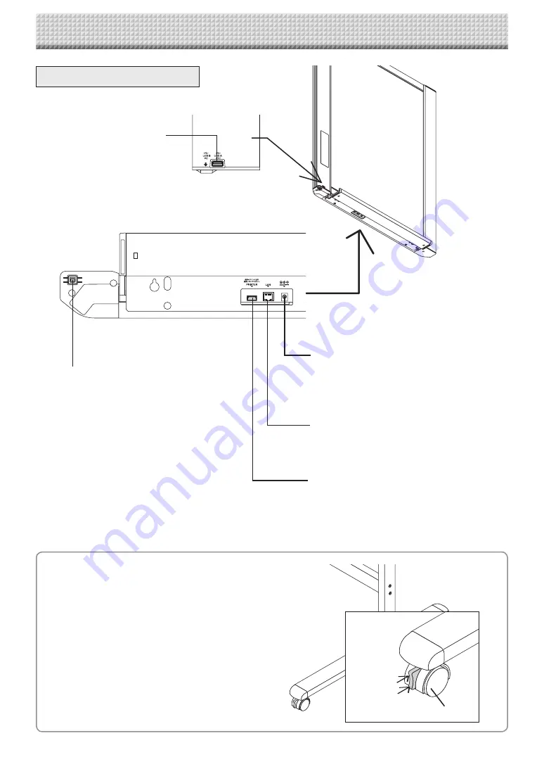
DC input connector
Connect this with the DC plug end of the AC
power adapter. (See Page E-52.) (Only connect
the supplied AC power adapter; nothing else.)
The connector is located on the bottom surface
of the main unit.
The diagram view is seen from the bottom.
Locking/unlocking the stand’s casters
After installation, lock the casters with the stoppers. When mov-
ing the stand, unlock the caster’s stoppers.
The stoppers are locked when the bottom is pressed. Press the
top to unlock them.
* This illustration does not show the printer or connec-
tion cords.
Personal computer (PC) dedicated
USB port (Type B)
Connect this with the USB port (type A) of the PC.
This is used for simplified network settings of the
main device. The scanned image can also be cop-
ied to the personal computer.
(See page E-17, E-38.)
LAN terminal (RJ-45)
Connect a LAN cable commercially available.
Printer connector (USB port Type A)
Connect this with the USB connector of the printer
(See Page E-52).
(The printer connector is dedicated for use with a
printer; use it only with a printer.)
USB memory port (type A)
Connect a USB memory stick commer-
cially available.
Scanned images can be saved.
(See page E-40)
Input/output terminals
Unlock
Lock
Caster
Summary of Contents for NF-20
Page 53: ......
Page 54: ...26 5675 13E...


