background image

 19

9. NAMES AND FUNCTIONS OF THE MENU AND

THE SUPERIMPOSED IMAGE DISPLAY SCREEN

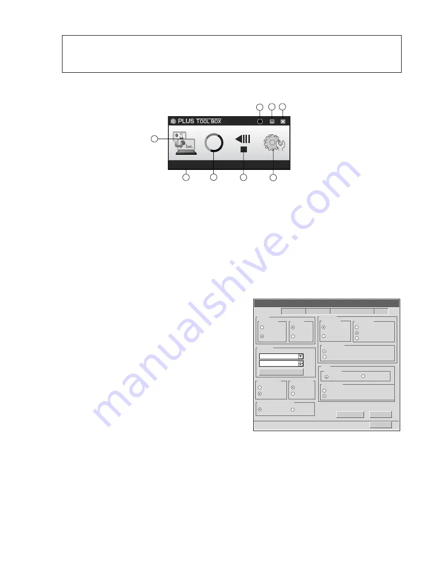
9-1. Menu

 Main Menu

Scan button

Displays Obtain annotated image dialogue box.
Yes:

Starts the capture of the image (projected by the projector) that is displayed on the personal com-
puter screen, and the hand drawn image of the sheet surface.

No:

Starts the capture of only the hand written and drawn image of the sheet surface. There will not be
superimposing with the image projected by the projector.

(Close): Closes the projection image superimposed screen.

Mark button
Switches the display of the positioning O marks of the projection image.
Each click switches between “Display” and “Hide”.
The default setting is “Display”.

Feed/Stop button

Scrolls the sheet one page to the left. When pressed
while scrolling, the sheet returns to the start position.

Setup button
Click this to display the settings screen.
The settings screen consists of the “Hardware Setup”,
“Capture Setup”, “Header/footer”, “Copyboard
Firmware Update” and “Security” tabs.
Click a tab to switch to the corresponding screen.
Note:

To set the “Security” settings, contact you nearest
PLUS Vision sales office, dealer or store.

Hardware Setup:
Set the Captureboard’s operating environment here.

2008/09/18

18:20:26

JPEG

PDF
PNG

Setup

Hardware Setup

Output

Color Mode

Time Day

Setup

Close

Density

Black & White

Color

Standard

Dark

Disable

Print

High Resolution

Match Paper Size

Original Image

Match Paper Size

Original Image

Scan Data

File Format

Resolution

Aspect Ratio

Default

Read current Date and Time

Capture Setup   Header/Footer   Copyboard Firmware Update  Security

Paper Size

A4

Letter

Aspect Ratio

Header/Fooder

Disable

Disable

Enable

Enable

Disable

Enable

Erase Reminder

Color Moder Restrication

CaptureBoard C-12W

?

V2.0

8

3

4

5

6

7

1

2

Main menu

Summary of Contents for CaptureBoard C-12S

Page 1: ...Captureboard C 12S C 12W SERVICE MANUAL ...

Page 2: ...ES AND FUNCTIONS OF THE MENU AND THE SUPERIMPOSED IMAGE DISPLAY SCREEN 19 9 1 Menu 19 9 2 Superimposed Image Display Screen 21 9 3 Superimposing Captured Images 22 9 4 Fine Adjustment of the Captured Image 26 9 5 Settings 27 9 6 Hardware Setup 28 10 TROUBLE SHOOTING 31 11 DISASSEMBLY AND ASSEMBLY 32 11 1 Tools Required 32 11 2 Caution 32 11 3 Disassembly and Assembly Procedures 32 11 4 Disassembly...

Page 3: ...opping or a person from falling down 1 2 Cautions during Disassembling and Assembling 1 This equipment contains parts under high voltage When doing repairs make sure that power plug is pulled out to insure safety 2 Make sure that parts screws and wiring etc are returned to their original positions Tube tape and other insulation materials have been used for safety reasons The internal wiring has be...

Page 4: ... sheet surface 2 4 dots mm 60 dpi or equivalent Sub scanning direction horizontal sheet surface 2 4 dots mm 60 dpi or equivalent Black white approx 15 s Black white approx 20 s Color approx 23 s Color approx 31 s USB Flash memory 2 FAT 12 16 32 PNG JPEG and PDF format USB1 1 or USB2 0 full speed mode 3 ON Standby Print Save Reprint Color Density Feed Stop Density Color 7 Segment Status of PC conne...

Page 5: ... one Captureboard to one personal computer DC 24V PRINTER PC To the RGB input connector of the projector Captureboard USB cable supplied with the unit Projector Personal Computer USB Monitor Output RGB Input To the PC dedicated USB port Type B To the personal computer USB port Type A To the RGB output Display connector of the personal computer ...

Page 6: ...panel Pen tray Stand 1 This stand supports the captureboard Effective aea The area that can be copied is the gray area of the diagram Note It might not be possible to print or memory to USB personal computer any portions that are written outside effective area Effective area approx 10 mm approx 10 mm approx 10 mm approx 10 mm Printer table The printer is placed here AC adapter box Store the AC pow...

Page 7: ...ent To use these functions first install the drivers and software on the included CD ROM onto the computer Printer connector USB port Type A Connect this with the USB connector of the printer The printer connector is dedicated for use with a printer use it only with a printer The connector is located on the bottom surface of the main unit The diagram view is seen from the bottom Locking and unlock...

Page 8: ...Reminder function has been set the sheet moves to the surface that has not yet been erased before the power turns off 1 1 Depending on the usage method the Erase Reminder function may not operate properly 5 Feed button Scrolls the sheet one screen portion left then stops automatically 6 buttons Time Setting Press the button or the button and perform the setting of the date time 7 Print button Move...

Page 9: ...into the main unit There is no available space A printer that is not supported by the captureboard has been connected This is the state in which calibration data is not written An error has arisen when setting the time Connect the printer properly and switch on the printer power Turn the power of the printer off and then on again and load the printer with A4 paper Read the printer instruction manu...

Page 10: ...nalize When F4 is displayed the captureboard is in the printing ratio setting mode 3 Press the Feed button to select the equal ratio mode Check that the lamps are lit or off as indicated at Lamps when the captureboard is set to print in equal ratio above then press the Save button to finalize The dot next to the F4 dot flashes for several seconds To restore the captureboard to print with the image...

Page 11: ...e mode Press the or button and make the adjustment 4 Press the Print button to confirm There is a change to the next setting mode Repeat steps 4 and 5 to set the current time 5 Completion To quit the time setting mode press the Print button Pressing the ON Standby button during operations 2 to 4 will cancel the incomplete settings and return to the time prior to starting the settings Preparation C...

Page 12: ...n select 11 the month and press the Print button to finalize There will be a change to the day setting mode display 6 Press the button or the button select 08 the day and press the Print button to finalize There will be a change to the hour setting mode display 7 Press the button or the button select 14 the hour of the 24 hour display and press the Print button to finalize There will be a change t...

Page 13: ... and Lamp Statuses Function number F1 is not used Nothing will happen when the Feed button is pressed 4 Quitting the function settings mode Press the ON Standby button to return to the normal mode The display window returns to the normal mode OP or PC The captureboard includes such advanced functions as the Erase Reminder function that can be set directly using the operation buttons on the capture...

Page 14: ...size Setting of printing paper size Resolution Setting of resolution for images stored in the memory and images transferred to the computer Image format Setting of format of images stored on the USB memory device Restrict color mode Setting for disabling printing storing in the color mode Test print Print copyboard s pre stored test pattern Factory reset Reset all the settings to their factory def...

Page 15: ...of PC Equipment required including software Program file for C 12 PC main set USB terminal 1 1 or more Software C 12 series PLUS TOOLBOX has been installed USB cable 1 Save a program file example c12_01_00 for C 12 in PC 2 Display the main menu of software PLUS TOOLBOX in PC 3 Pull out the power plug when the power plug of the main set is connected to the wall outlet 4 Connect the power plug of th...

Page 16: ...Display example 01 4 A program is updated when you press the Save button of the C 12 main set During program rewrite The display window blinks during display 5 A new program version is shown on the display when update is completed Display example 01 6 Remove the USB memory and press the Power button of the C 12 main set to turn off the power 7 Pull out the AC adaptor of the C 12 main set once inse...

Page 17: ...ler is started the User Account Control dialog box is dis played Select Continue and continue with the installation Windows Security Would you like to install this device software Name Jungo Jungo Publisher Jungo LTD Always trust software from Jungo LTD You should only install driver software from publishers you trust How can I decide which device software is safe to install Don t Install Install ...

Page 18: ...click Next N when using Win dows XP Start the installation of the USB driver Note Installation will be completed automatically with Windows 2000 Windows Vista PLUS TOOLBOX InstallShield Wizard Cancel Finish Back InstallShield Wizard Completed The InstallShield Wizard has successfully installed PLUS TOOLBOX Click Finish to exit the wizard PLUS TOOLNOX Installer Information You must restart your sys...

Page 19: ...on the OS to display the Add or Remove Programs Properties screen 3 Select PLUS TOOLBOX from among the list displayed and click Change Remove to display the Add or Remove wizard screen 4 Selecting the Remove radio button of the wizard and clicking Next will start the uninstallation Note Add or Remove Programs will be displayed for Windows XP Vista When using Windows Vista each time the uninstaller...

Page 20: ...utton and then the print button during button operation 2 Calibration mode start 2 SPC 1 Calibration is executed when you press the Print button during button operation 3 CCD adjustment mode 6 SPC 1 An RGB adjustment mode sequence is performed LED lights in red during CCD adjustment when you press the additional Reprint button during button operation 4 Program version display Internal Information ...

Page 21: ...sheet returns to the start position Setup button Click this to display the settings screen The settings screen consists of the Hardware Setup Capture Setup Header footer Copyboard Firmware Update and Security tabs Click a tab to switch to the corresponding screen Note To set the Security settings contact you nearest PLUS Vision sales office dealer or store Hardware Setup Set the Captureboard s ope...

Page 22: ...ing Close Closes the settings screen Header Footer This is used for the creation or editing of headers and footers Copyboard Firmware Update Use this to update the Captureboardís internal program Help Click this to display the operating instructions Minimize Click this to minimize the menu screen displaying it as an icon on the task bar Close Click this to exit the program Device indication This d...

Page 23: ...nt when projecting a superimposed image with the projector The default setting is Window size Captureboard Capture Screen Execution of the scan operation displays the handwritten image data of the captured sheet surface Personal Computer Capture Screen Pointers to of the projected image are displayed by left clicking on the personal computer capture screen and hidden by right clicking Drag the poi...

Page 24: ...the F1 to F12 keys The F1 to F12 keys will differ depending on the manufacturer of the personal computer Please see the Help menu of your personal computer for details An attempt to superimpose with a projection image that has used the digital enlargement function of the projector will not result in an enlarged image Set up the projector so that it is level to prevent a projection image that is on...

Page 25: ...ote Check whether this machine and the personal computer are properly connected PC is displayed in the dis play window of the main unit control panel when the equipments are properly connected 4 Trace with a marker having the same color as the marks of the Projected four corners Properly draw the marks in the color of the projected m marks This software uses the marks drawn on the sheet sur face t...

Page 26: ... scanning density When Header Footer is set to On in Hardware Setup the header footer information is displayed on the combined image In this case this information is saved and printed 7 Click Save to Save When saving for the first time clicking will display the personal computer Save as box Select Save location File type enter the file name then click the Save button Select the file type PNG JPG o...

Page 27: ...re Note When other TWAIN compatible applications are used to cap ture the picture data while PLUS TOOLBOX software is run ning following procedure should be taken When PLUS TOOLBOX is running or its icon appears on the Windows task bar and the picture data is attempted to be captured using other TWAIN compatible application software below error message may pop up In this case right click the PLUS ...

Page 28: ...which is the screen output for projection by the projector When the keystone distortion horizontal distortion vertical distortion of the projection image is adjusted it will be slightly smaller than the output screen from the personal computer screen The size of the image changes depending on the degree of distortion compensation This is a result of the compensation characteristics of the projecto...

Page 29: ... has been selected an arbitrary marker color from among the four colors of red green blue and black can be used for drawing the positioning mark Recognition is judged solely by the shape of the O mark that has been drawn with the marker Writing or drawing a diagram that resembles the O mark may result in a position of the projection image cannot be properly recognized When one color has been selec...

Page 30: ... with the standard set ting set to Dark Aspect Ratio setting Selection is permitted only with a captureboard of the wide type Select the vertical horizontal aspect ratio for printing When Original Image is selected the image is printed with the same aspect ratio as on the captureboard s sheet surface When Match Paper Size is selected the image is com pressed in the horizontal direction to the same...

Page 31: ...ion is clicked a gray cursor is displayed over the hours 2 Click or in the time section to choose the current hour 3 Now click the minutes 09 in this example to display a gray cursor over the minutes 4 Click or to choose the current minutes 5 Now click the seconds 18 in this example to display a gray cursor over the seconds 6 Click or to choose the current seconds Note The clock starts when the Se...

Page 32: ...om of the sheet and the same information will be printed on any page This is called a header when the information is at the top or a footer when the information is at the bottom The header footer is created with this software and stored in the captureboard See Creation and Editing of Headers Footers for details The actual printout color may differ from the original image depending on the printer m...

Page 33: ...f a printer is exhausted The printer is not connected The Main Board Assy is defective No Is the object written in the board printed normally No A black line is put in printing Out of adjustment of CCD Unit Slight It is improved by calibration Out of adjustment of CCD Unit Severe Perform the CCD adjustment again Dust adheres to the mirror of the board body Printing becomes blurred The marker writt...

Page 34: ...d at the sharp edge of a frame during disassembly and assem bly See 14 Wiring Diagram and 15 Parts List for the parts name or wiring The point especially requiring attention when handling parts or performing disassembly and assembly con tains a caution Be sure to follow this caution 11 3 Disassembly and Assembly Procedures START LED Unit Back Panel Main Board Assy Frame Cover Unit Endless Sheet Sh...

Page 35: ... for ten years or more For a new Main Board Assy of C 12 type volume con trol R82 is not installed because of automatic adjust ment 11 4 Disassembly and Assembly This section describes one example of disassembly and assembly procedures For the actual operation disas semble and assemble the required parts with reference to 11 3 Disassembly and Assembly Procedures 1 Remove the Back Panel See Figs 1 ...

Page 36: ...cable tie SG SP100 and fix them to the stiffener Fix the core so that it does not move Note Pass only a CCD cable through the DK core Do not wind a cable as in a standard model DK core installation and wiring CCD harness Wind the CCD harness onto the DK core by one turn Pay attention to the winding direction of a cable Put the clutch of the DK core Hole of DK core Pass the SW harness S or SW harne...

Page 37: ...ee Fig 7 1 Remove the S 8 and S 10 screws shown in Fig 7 2 Remove the S 5 screws shown in Fig 7 and then remove the Switch Box Unit Notes Be careful not to mistake the hole through which the Switch Harness is passed Pay attention to a kind of screw See Fig 8 Switch Box Unit S 8 S 10 Front Side Other Side Switch Harness S 9 S 9 S 2 S 2 S 2 S 2 Cap L Cap R Cap R Cap L ...

Page 38: ... in the portion A of Fig 10 Remove the Motor Harness earlier when the Sheet Frame Unit is removed Motor Harness Sheet Motor Assy S 3 S 3 8 Remove the Sheet Motor Assy See Fig 11 1 Remove the S 3 screws shown in Fig 11 Note Adjust the tension of the Timing Belt when the Sheet Motor Assy is installed See 13 Adjustment S 2 S 1 S 2 S 20 S 20 S 1 S 1 S 6 S 6 S 2 S 2 S 1 Frame Cover Upper Frame Cover Si...

Page 39: ...Remove the LED Harness as shown in Fig 16 2 Remove the S 3 screws as shown in Fig 16 3 Remove the LED Unit as shown in Fig 16 Note Use the parts assembled in a factory during replace ment of an LED unit Calibration is required after replaced Endless Sheet 9 Remove the Sensor Board Unit See Fig 12 1 Remove the S 3 screws shown in Fig 12 and then remove the Sensor Board Unit Note Be careful not to d...

Page 40: ...ional although the printer type may differ from that of the connection diagrams e g a built in type or assembled type the connections should be performed based on the same main points In accordance with the printer specifications Appearance of printer is for illustration purposes 12 CONNECTION TO THE SET 12 1 Connecting the main unit and printer Connect as shown on the diagram below Do not yet con...

Page 41: ... unit and printer should not hang down Place any extra cable inside the AC adapter box 2 Place the AC power adapters of the main unit and printer in the AC adapter box Catch the hooks on the ends of the AC adapter box onto the bottom of the left and right brackets the L shaped part To catch the hooks insert the AC adapter box from the front of the printer table and pull to the rear This catches th...

Page 42: ...200V power cord 1 Attach the cable cover s according to the type you have purchased Peel off the backing paper from the cable cover and attach the cable cover firmly to the bracket When the main unit is installed on a wall Attach the cable cover to the side of the bracket For the wide type also attach one of the cable cov ers specifically for the main unit to the bottom of the main unit Insert the...

Page 43: ...he main unit Cable cover specifically for the main unit Wall power outlet AC power adapter s power plug AC power adapter s power plug Wall power outlet AC power adapter s power plug Wall power outlet Back surface Back surface Back surface Do not use the cable cover specifically for the main unit if mounted on the right as seen from the back of the printer table Cable cover Accessory for stand kit ...

Page 44: ...bration Scale when writing a line in the center position See detail drawing 2 Put a C 11 Calibration Scale to the lower right corner of the main unit frame for use when writing a line in the lower position Detail drawing 1 Detail drawing 2 Fig 1 Adjustment Pattern Sheet O hole Horizontal line for focus adjus tment Vertical line for trig angle adjustment Fig 2 CCD Adjustment Pattern Drawing the CCD...

Page 45: ...r Ch2 to J3 Set the Ch1 mode to 1 0 V DIV AC Set the trigger to 2 V DIV DC Set the sweep to 400 500µsec DIV Set the trigger to EXT or Ch2 Only Ch1 is displayed For a new Main Board Assy volume control R82 is not installed because of automatic adjustment ADJUSTMENT J1 J2 J3 J4 3 Temporary focus adjustment Adjust the lens to the reference position and fix the two lens fixing screws temporarily See F...

Page 46: ...ton The LED repeatedly lights in green blue and red when you press the Reprint button See Figure 5 5 Adjustment of oscilloscope Adjust the trigger level and Ch1 vertical position so that a CCD waveform appears on the oscilloscope display with the light source LED turned on in red Adjust the horizontal position luminance and focus See Figure 6 Fig 5 Adjustment mode sequence Fig 6 CCD waveform Adjus...

Page 47: ...Holder smoothly moves and does not float from the Lens Holder Fig 7 CCD adjustment screws Fig 8 CCD waveform Monitoring angle adjustment Lens Focus Ring Plate CCD Holder CCD PCB Lens Holder CCD fixing screws Two positions CCD Position adjustment screws Two positions Lens fixing screws Two positions Install a lens so that the lens marking is located horizontally and toward you Locking compound appl...

Page 48: ...so that the displayed waveform is sharp Adjust the focus and fix the lens fixing screws see Figure 4 See Figure 9 Fig 9 CCD waveform Focus adjustment 8 Waveform confirmation The brightness of the light source LED is automatically adjusted by CPU when you press the Feed button in the CCD adjustment mode Confirm that the shape of the waveform automatically adjusted for each color R G B is equal on t...

Page 49: ...le Detail drawing 1 100 10mm 35 3mm 100 5mm Cautions during calibration 1 Confirm that sheet O hole for page management of a sheet exists at the lower right corner There are two holes Use a hole far from seam portion of the sheet 2 Write a line using a black marker 3 Write only upper and lower horizontal lines Do not write a vertical line A C 11 Calibration Scale is used in this case 4 The Hole lo...

Page 50: ...t level of LED again in the position where reference data is gotten 2 4 g Get the reference data 2 5 h Move the sheet so that the center of a horizontal line is almost positioned in the image pickup range of CCD 2 6 i Write data into flash ROM 2 7 Operation is normally terminated when AA is displayed Turn off the power in this case SPC indicates the non lighting state O O is displayed respectively...

Page 51: ...djustment See the illustration shown below Fix the Sheet Motor Assy tentatively and measure the tension of a timing belt using a spring balance Move the Sheet Motor Assy and fix it in the position where proper load is obtained The proper load is 0 3 to 0 6 kgf with the timing belt bent by approximately 1 mm Spring Balance Deflection Value Controller Timing Belt Sheet Motor Assy ...

Page 52: ...tion PC CN10 CN2 CN1 CN1 CN3 CN2 CN9 CN8 CN5 CN2 SW Board Assy CN12 CN1 LED1 LED2 LED3 LED2 12pin 6pin 22pin LED5 Main Board Assy CCD Board Assy Sheet Motor Assy Sensor Board Unit LED Unit AC Plug Adapter USB Host printer USB Host memory 5pin ...

Page 53: ...51 11 PARTS LIST 1 Overall configuration 1 S 1 S 9 A B A B 2 S 7 S 7 S 1 S 9 4 3 5 5 4 7 6 6 S 2 S 2 S 2 S 2 ...

Page 54: ...configuration No PARTS NAME PARTS No Q ty REMARK S W 1 Frame Cover 1 2 Sheet Unit 1 3 Board Unit 1 4 Cap L 723122100 723122100 2 5 Cap R 723122200 723122200 2 6 Back Panel Corner 2 7 Back Panel S 301101 1 Back Panel W 301102 1 ...

Page 55: ...53 PARTS LIST 2 Frame Cover Section S 2 S 1 S 1 S 1 14 18 9 8 14 S 8 S 10 10 S 1 12 S 6 S 2 11 S 6 S 2 13 14 19 20 S 11 15 S 2 S 11 15 14 16 17 ...

Page 56: ...1 13 Cover R 723120800 723120800 1 14 Cover Plate 715201000 715201000 4 15 Upper Cover Plate 723131300 723131300 2 Switch Box Unit C 12S J 1 Japan Only 16 Switch Box Unit C 12W J 1 Japan Only Switch Box Unit C 12S O S 723090053 1 Switch Box Unit C 12W O S 723090054 1 17 Switch Panel C 12 J 1 Japan Only Switch Panel C 12 O S 723156400 723156400 1 18 Name Plate 723150100 723150100 1 19 Captureboard ...

Page 57: ...55 PARTS LIST 3 Sheet Frame Section 21 22 S 3 S 3 24 23 25 26 S 3 27 ...

Page 58: ...22 Sheet Frame C 12S 1 Sheet Frame C 12W 1 Sheet Frame Unit C 12S 301209 1 Sheet Frame Unit C 12W 301210 1 23 Motor Harness S 715257800 1 Motor Harness W 715258300 1 24 Sheet Motor Assy 718501200 718501200 1 25 Vibration Proof Rubber 718209300 718209300 1 26 Motor Bracket 715353300 715353300 1 27 Sensor Board Unit 715260900 715260900 1 ...

Page 59: ...arts Supply 29 LED Unit 301109 301109 1 30 CCD Unit 715090013 715090013 1 31 Main Board Assy C 12 723511500 723511500 1 32 CCD Harness 715257700 715257700 1 33 LED Harness 715257900 715257900 1 34 DK Core 714890100 714890100 1 35 Sensor Harness 715260600 715260600 1 36 Ferrite Core 715251512 1 Wide Only S 3 S 3 S 3 S 3 S 3 S 4 S 3 28 29 31 33 30 34 35 36 32 ...

Page 60: ...58 PARTS LIST 5 Accessories Section PLUS P L U S P L U S P L U S P L U S 37 38 39 42 43 44 45 40 41 46 47 48 49 50 51 52 54 53 55 60 61 62 63 56 57 58 59 ...

Page 61: ...rker Blue 44574 44574 1 Drywipe Marker Green 44575 44575 1 47 Eraser ER 44369 44369 44369 1 48 Wall Mount Plate 715359900 715359900 4 49 AC Adapter 715259000 715259000 1 AC Adapter 723582100 723582100 1 USA Oceania Only Power Cable 2 5m EU 715259200 715259200 1 Power Cable 2 5m UK 715259300 715259300 1 50 Power Cable 2 5m US 715259400 715259400 1 Power Cable 2 5m AU 715259500 715259500 1 Power Cab...

Page 62: ...60 PARTS LIST 6 Carton Packing 64 66 67 65 68 69 70 71 73 72 ...

Page 63: ...n Upper M 12S 1 Carton Upper M 12W 1 65 Carton Lower M 12S 1 Carton Lower M 12W 1 66 Corner Packing Upper L 1 67 Corner Packing Lower L 1 68 Corner Packing Upper R 1 69 Corner Packing Lower R 1 70 Accessory Box 1 71 Push Accessory Box S 1 Push Accessory Box W 1 72 Printer Platform Pad A 1 73 Push Adapter Box 1 PARTS LIST ...

Page 64: ...PARTS LIST 7 M 12 T T 1 T 1 T 2 T 2 T 3 T 3 T 4 T 4 T 5 T 5 T 6 T 7 T 8 T 8 T 9 T 10 T 10 T 10 T 10 T 10 T 11 T 12 T 13 T 14 T 14 T 14 T 14 T 15 S 12 S 13 S 14 S 12 S 13 S 14 S 12 S 13 S 14 S 12 S 13 S 14 ...

Page 65: ...2 Carton UNIT Stand 301207 301207 1 T 6 Carton Upper Stand 1 T 7 Carton Lower Stand 1 T 8 Packing Set Stand 2 T 9 Assembly Manual Stand O S 1 No Parts Supply Assembly Manual Stand JPN 1 No Parts Supply T 10 Screw Unit 723090012 723090012 1 T 11 Printer Steady Stand 715353700 715353700 1 T 12 Edge Bush 715353800 715353800 1 T 13 Stabilizer UNIT M 12 301208 301208 1 T 14 Pipe Cap 723321100 723321100...

Page 66: ...610 8 Binding Head S 6 M3 8 P Tight Cross Recessed 953230850 953230850 6 Binding Head S 7 M3 6 Cross Recessed Binding Head 951230650 951230650 28 S 8 M4 10 P Tight Cross Recessed 953241010 953241010 3 Binding Head S 9 M4 12 Cross Recessed Binding Head 951241250 951241250 6 10 Standard 6 Wide 10 S 10 M4 15 P Tight Cross Recessed 953241510 953241510 3 Binding Head S 11 M4 6 Cross Recessed Binding He...

Page 67: ...65 16 REVISION HISTORY No Revision History Revision page Date 1 2 3 4 5 6 7 8 9 10 11 12 13 14 15 16 17 18 19 20 ...

Page 68: ...66 ...

Reviews: