23 Once test weights are removed, to visually inspect lift / brackets / all
fastenings, if necessary check with tools (Calibrated torque wrench)
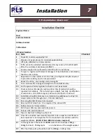
24 Cosmetics of the installation are standardised by the following:
o
Operation board to be screwed in with appropriate fastenings
o
Handset located in standard position
o
Handset cable correctly wired through door and door hinge
o
Door or cab switch correctly installed and adjusted
o
Hydraulic pump topped up to correct level of fluid
o
All cabling correctly tightened and exposed ends rubber booted
o
Conduit in all cables (70 amp)
o
Isolator relay routed on bracket
o
Power pack is fused correctly as supplied by the factory, any
modifications required or witnessed should be fully documented
and reported to all parties concerned.
o
Hand pump handle should be correctly clipped to power pack or
customer’s preferred location
o
Pump c/s link wire taken out
25 Lift to be fully cleaned down and checked in accordance with new
equipment automotive supply. (Air blow and silicone, lubricate)
26 Remaining photographs to be taken of lift fully up / lift fully down / lift
cassette box from under vehicle, to include weight test photo. Photos to
be emailed to Head Office
27 Relevant manager to be contacted to inspect installation and sign off
relevant paperwork
28 Work area to be cleaned to a satisfactory level
29 Tools, weights and pallet to be removed back to Engineer’s vehicle
30 Engineer to sign out accordingly with the site policy
Summary of Contents for Access ACC-1150
Page 7: ...1 1 5 Heath Safety Scooters General ...
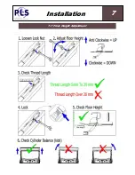
Page 23: ...7 7 7 Floor Height Adjustment Installation 7 INSTALLATION 7 6 Floor Height Adjustment ...
Page 25: ...7 7 9 Weight Test Installation 7 INSTALLATION 7 8 Weight Test Dynamic Dynamic ...
Page 30: ...Thread Size Tightening Torque Nm Hydraulic Fitting BSP 1 8 17 0 1 4 34 0 3 8 47 0 ...
Page 31: ...8 8 1 Standard Operating Procedure Operation 8 OPERATION 8 1 Standard Operating Procedure ...
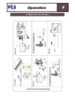
Page 32: ...8 8 2 Manual Override Procedure Operation 8 OPERATION 8 2 Manual Override Procedure ...
Page 35: ...10 10 2 Loler Service Maintenance ...
Page 44: ...13 13 1 Wiring Diagram Power Pack Diagrams 13 DIAGRAMS 13 1 Wiring Diagram Power Pack ...
Page 46: ...13 13 3 Hydraulic Diagram Diagrams 13 DIAGRAMS 13 3 Hydraulic Diagram ...
Page 82: ...15 Notes ...
Page 83: ...15 Notes ...


