7
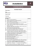
7.11 Installation Check List
Installation
Installation Checklist
Engineer Name:
Date:
Customer Details:
Address Contact:
Tel Number:
Lift Serial Number:
No Item
Checked
1
Check lift to order supplied by PLS
2
Dispose of any excess parts / materials appropriately
3
Lift to be collected in a timely manner
4
If lifts cannot be collected and delivered for any reason, PLS will dispatch
lift to the customer’s premises (UK ONLY)
5
Ensure enough time is allowed to install the lift in one full day
6
To sign in / register with relevant manager at Coach Builders, and abide by
the Site’s H & S Policy.
7
Dependent on the Customer’s H & S Policy, the Engineer maybe required
to provide a working on site risk assessment
8
Deliver the lift (s), plus tooling and test weights
9
To co-ordinate lift, tooling and weights to the installation bay
10 For the given vehicle, Engineer to check correct paperwork
11 Check vehicle is (Standard), anything other than (Standard) should be
reported immediately. This includes spare wheels, fuel tank, modification
of suspension, air conditioning unit, exhaust and all parts of exhaust
12 Installation should commence in correlation to guidelines set out by PLS
13 Hand control cable through door – Vehicle cable bush
14 Door plug (Nutrik) 20mm
ø
hole required.
15 Door switch 12mmø hole. One required if no cab switch?
16 Rubber boot on 70 amp isolator.
17 Drill chassis 20mmø, and used tube spacers.
18 Shroud nitto plastic taken off.
19 Tape on box back holding top sheet on
20 Once lift is installed and correctly adjusted, Loler inspection certificate to
be completed. A full weight test to be conducted in accordance with the
weight certificate. (BS:EN 1756-2-2004
15 minute creep test)
21 First weight test to be tested to 125% stated S.W.L load (I.e. 400kgs =
500kgs full test). Photographs are to be taken of the weight applied
22 After load test, pump should be reset to (400kgs < 425kgs max)
7
INSTALLATION
7.11
Installation Check List
Summary of Contents for Access ACC-1150
Page 7: ...1 1 5 Heath Safety Scooters General ...
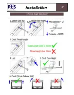
Page 23: ...7 7 7 Floor Height Adjustment Installation 7 INSTALLATION 7 6 Floor Height Adjustment ...
Page 25: ...7 7 9 Weight Test Installation 7 INSTALLATION 7 8 Weight Test Dynamic Dynamic ...
Page 30: ...Thread Size Tightening Torque Nm Hydraulic Fitting BSP 1 8 17 0 1 4 34 0 3 8 47 0 ...
Page 31: ...8 8 1 Standard Operating Procedure Operation 8 OPERATION 8 1 Standard Operating Procedure ...
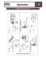
Page 32: ...8 8 2 Manual Override Procedure Operation 8 OPERATION 8 2 Manual Override Procedure ...
Page 35: ...10 10 2 Loler Service Maintenance ...
Page 44: ...13 13 1 Wiring Diagram Power Pack Diagrams 13 DIAGRAMS 13 1 Wiring Diagram Power Pack ...
Page 46: ...13 13 3 Hydraulic Diagram Diagrams 13 DIAGRAMS 13 3 Hydraulic Diagram ...
Page 82: ...15 Notes ...
Page 83: ...15 Notes ...


