background image

3

2

5

1

Note:

 O

il 

Supplied 

Separ

atel

y

10

9

11

12

PUM

CO

VER

7

6

PAR

TS 

LIST

ITEM

Q

TY

PAR

NUM

BER

DESCRIPTIO

N

1

1

ACCF

ABPM

P50840

ACC 

External

 Pump 

Br

ack

et

2

1

ACCHYDHO

S530-001-700

ACC 

O

uter 

Bo

Hose 

700

3

1

ACCHYDPM

PZEF12/24

RFP 

Encl

osed 

Pack 

12V/24V 

4

10.000 

g

CO

NO

T/0014

500g 

Petr

ol

eum 

Jel

ly

5

2

FA

SBL/1029

M

10 

60 

Hex 

Head 

Set 

Scr

ew

6

2

FA

SNT/1001

M

10 

Nyloc Nut

7

4

FA

SW

A/1001

M

10 

Pl

ai

W

asher 

Form 

A

9

1

CO

NL

B/0020

AF26 

Al

Foil

 w/on 

Label

Seri

al

 No

. (P

ack 350)

10

1

CO

NL

B/0002

WL

28 

LABEL 

LEGEND 

TESTED 

PACK 

350)

11

1

CO

NL

B/0003

Thi

W

ay 

Up 

PLS 

Blue 

Sti

ck

er 

12

1

ACC26469

Vi

nyl

 R

ound PLS 

Label

Note:

Fi

xi

ngs 

ma

vary

External

 Encl

osed 

Pack 

Horiz

ontal

 P

osi

tion

30

Summary of Contents for Access ACC-1150

Page 1: ...www passengerliftservices co uk Instruction Manual Access Van Lift ACC 1150 ACC 1200 ACC 1280 ACC 1300 ACC 1380 UK Version Revision 1 4 Year 2017 BS EN 1756 2 2004 and A1 2009 Access Van Lift ...

Page 2: ...Mounting Options 7 5 Checking the Power Pack Oil Level 7 6 Hydraulic and Electrical Fittings 7 7 Floor Height Adjustment 7 8 Bridge Plate Adjustment 7 9 Weight Test Dynamic 7 10 Weight Test Overload Drift Static 7 11 Installation Checklist 7 12 Torque Settings 8 OPERATION 8 1 Standard Operation procedure 8 2 Manual Override 9 CLEANING 9 1 Cleaning Instructions 10 SERVICE AND MAINTENANCE 10 1 UK Se...

Page 3: ...also includes the CE marking guarantee of the compliance of the device to the directives standards referred to the enclosed Declaration of Conformity The plate a facsimile of which is shown here is stamped with the data indicating the specific model and unit NOTE The Lift Serial number will be required for ALL correspondence with factory Uniformly Distributed LIFT SERIAL No OR SWL 400kg PASSENGER ...

Page 4: ...ents of this manual comply with the Directive 2007 47 EC and were drafted following the guidelines given in UNI 10893 2000 They also comply with the requirements of UNI EN ISO 10535 2007 and BS EN 1789 2007 and A2 2014 Data and drawings are indicative only with a view to the continuous development and updating of its products the manufacturer may modify the contents without notice It is prohibited...

Page 5: ...erforming all operational functions of lift Not impaired by the consumption of legal and or illegal substances such as alcohol and or drugs MENTAL Possess the required mental qualities characteristics sufficiently to ensure safe operation of lift in a safe and controlled manner Examples include Understanding application of the safety rules and procedures while operating the lift Be constantly awar...

Page 6: ...his manual is read and fully understood by all potential lift operators before operating the lift No operator will use the lift if they believe it is unsafe and doing so could injury themselves or others they MUST report their concerns directly to their manager or PLS 1 General ...

Page 7: ...1 1 5 Heath Safety Scooters General ...

Page 8: ...ess Van Technical 2 Technical 2 1 Main Components Access Van Power Pack Carriage Box Lock Umbilical Handrail Roll Off Ramp Top Sheet Extension Platform Cassette Box Box Bridge Plate Arm Pump Mounting Bracket Manual Pump Handle ...

Page 9: ...m 1510mm 1510mm D 825mm 925mm 825mm 925mm 825mm 925mm 825mm 925mm 825mm 925mm E 360mm 425mm 470mm 425mm 470mm F 370mm 400mm 470mm 400mm 470mm G 95mm 100mm 70mm 100mm 70mm 2 Technical 2 2 Dimensions Access Van B Box Widths D Platform Widths E Max Up F Max Down A Box Length 175mm 200 550mm Bridge Plate Variations to Suit Vehicle C Platform Length G Platform Overhang To Shroud At Max Up Overall Lengt...

Page 10: ... 2 3 Technical Data Access Van Note Lift weight not including Power pack Installation Kit The Lift is designed To Transport Two walking passengers The operator should not attempt to transport more than two people at a time of increased risk of passenger discomfort The passengers also may require extra space for mobility devices such as sticks and frames Or One person in a wheelchair with or withou...

Page 11: ... only be used by an authorised and trained operator known as the accompanying person who possesses the knowledge and physical requirements to safely perform operations with disabled persons Anything that is not specifically referred to in chapter 3 1 is considered IMPROPER USE 3 PRODUCT USE 3 1 Intended Use THE MANUFACTURER DECLINES ALL RESPONSIBILITY FOR DAMAGE CAUSED TO PERSONS OR PROPERTY OR TO...

Page 12: ...USE 3 2 Improper Use IT IS FORBIDDEN to climb onto the lift or any of its parts and go up or down while standing It is advisable to always attempt to use the lift on flat level ground No angle of more than 5 from level in any direction should be attempted THE MANUFACTURER DECLINES ALL RESPONSIBILITY FOR DAMAGE CAUSED TO PERSONS OR PROPERTY OR TO THE LIFT ITSELF DUE TO ANY USE OTHER THAN THAT DESCR...

Page 13: ...rail Guard Standard 3 Roll Of Ramp Standard 4 Bridge Plate Standard 5 Anti Slip Surface Cleats Standard 6 Handrail Extension Optional 7 Door Safe Optional 8 Stop Safe Optional 4 SAFETY DEVICES 4 1 Description of Safety Devices Access Van 1 2 3 4 5 7 8 6 Standard Standard Standard Standard Standard Optional Optional Optional Roll Off Ramp Anti Slip Surface Cleating ...

Page 14: ...s Stickers ACC25130 DB Access Operation Instructions Board ACC 26469 PLS 321 REFLECTIVE REFLECTIVE ACC 26469 Uniformly Distributed LIFT SERIAL No OR SWL 400kg PASSENGER LIFT SERVICES LTD Tel 0121 552 0660 Unit 2 Summit Crescent Ind Est Off Roebuck Lane Smethwick West Midlands B66 1BT Website www passengerliftservices co uk ...

Page 15: ...parts are intact during transportation With great care examine all devices to ensure they haven t been damaged during transportation and all parts haven t been tampered or removed Ensure all documentation required for installation has been supplied 6 2 Storing The Lift If the lift is not used proceed as follows Transport lift to an appropriate storage area free from atmospheric agents elements Ens...

Page 16: ...ong the 4 sides of the base of the packaging remove tape and ensure waste cardboard is recycled For wooden crates remove nails from top panel and those present on the side walls STAFF REMOVING THE PACKAGING MUST WEAR SAFETY SHOES WITH STEEL TOE CAP AND NON SLIP SOLES AND GLOVES 6 3 Handing 6 LOGISTICS All lifting and short workshop distance transportation of packages lifts must be carried out usin...

Page 17: ... include engineering quality control specialist equipment information instruction Customer responsibilities maintained Action Plan Controls All lifts are supplied with safety instructions and safe operating procedures with visual instruction for the automatic and manual operation of lifts Safety instruction is also generated and supplied for the use of lifts by scooters and large powered wheelchai...

Page 18: ...X BOLT WASHER HOLE WASHER NYLOCK HOLE WASHER NYLOCK HOLE BOX LOCK REAR X FRONTY VEHICLE FLOOR REAR X FRONT Y BOX LOCK BOX SECTION CHASSIS VIEW ON LHS OF THE BOX REAR SECTION OF VEHICLE BOX FRONT MOUNTING BRACKET G VIEW ON RHS OF THE BOX REAR SECTION OF VEHICLE BOX SECTION LARGE CHASSIS VEHICLE FLOOR BOX REAR OF BOX TO BE 15MM LOWER THAN THE FRONT BUMPER PLATFORM BUMPER ARMS REAR MOUNTING BRACKET U...

Page 19: ...OCK FRONT MOUNTING BRACKET VEHICLE FLOOR BOX BUMPER ARMS PLATFORM G VIEW ON RHS OF THE BOX REAR SECTION OF VEHICLE OPEN SECTION CHASSIS LIFT DIRECTION DETAIL A THERE ARE USUALLY TWO OR MORE HOLES IN THE END OF THE CHASSIS VEHICLE FLOOR REAR X BUMPER REAR MOUNTING BRACKET FRONT Y BOX LOCK UMBILICAL COVER FRONT MOUNTING BRACKET OPEN SECTION CHASSIS VIEW ON LHS OF THE BOX REAR SECTION OF VEHICLE BOX ...

Page 20: ...7 7 4 Power Pack Mounting Options Installation Horizontal Mounting On Back Vertical Mounting PLUG CAP Horizontal Mounting On Side PLUG CAP PLUG CAP Mounting mounting brackets will vary contact pls ...

Page 21: ...ipe any residual oil form the dip stick using a clean dry cloth Insert the dip stick fully into the Oil filler remove and then check to see where the oil is indicated on the dip stick If the oil is on the min mark then top up slowly with PLS Blue oil only repeat checking procedure as above until the oil is mid way between min max levels 7 INSTALLATION 7 5 Checking the Power Pack Oil Level ...

Page 22: ...tings Installation Pressure Pressure Hydraulics Fitting Electrics Fitting Battery LIVE Red 16 mm2 min Battery connection Circuit Breaker MUST BE LOCATED CLOSETOTHE BATTERY MAX 200MM AWAY 6Way Handset Battery NEG Black 16 mm2 min UP DOWN ...

Page 23: ...7 7 7 Floor Height Adjustment Installation 7 INSTALLATION 7 6 Floor Height Adjustment ...

Page 24: ...7 7 8 Bridge Plate Adjustment Installation Access is gained from top of Platform 7 INSTALLATION 7 7 Bridge Plate Adjustment ...

Page 25: ...7 7 9 Weight Test Installation 7 INSTALLATION 7 8 Weight Test Dynamic Dynamic ...

Page 26: ...7 7 10 Weight Test Installation Overload 7 INSTALLATION 7 7 Weight Test Overload Load Test 7 9 Weight Test Overload Drift Static Drift Static ...

Page 27: ...correct paperwork 11 Check vehicle is Standard anything other than Standard should be reported immediately This includes spare wheels fuel tank modification of suspension air conditioning unit exhaust and all parts of exhaust 12 Installation should commence in correlation to guidelines set out by PLS 13 Hand control cable through door Vehicle cable bush 14 Door plug Nutrik 20mmø hole required 15 D...

Page 28: ...ectly as supplied by the factory any modifications required or witnessed should be fully documented and reported to all parties concerned o Hand pump handle should be correctly clipped to power pack or customer s preferred location o Pump c s link wire taken out 25 Lift to be fully cleaned down and checked in accordance with new equipment automotive supply Air blow and silicone lubricate 26 Remain...

Page 29: ...0 140 0 M14 132 0 185 0 220 0 M16 200 0 285 0 340 0 Thread Size Tightening Torque Nm Property Class HTS Hex Flange 8 8 10 9 12 9 M6 9 0 14 7 16 8 M8 20 0 35 6 41 0 M10 40 0 70 6 81 0 Thread Size Tightening Torque Nm Property Class Stainless Steel A2 70 A4 80 M4 2 6 3 5 M5 5 1 6 9 M6 8 8 11 8 M8 21 4 28 7 M10 44 0 58 0 M12 74 0 100 0 M14 119 0 159 0 M16 183 0 245 0 7 INSTALLATION 7 11 Torque Settin...

Page 30: ...Thread Size Tightening Torque Nm Hydraulic Fitting BSP 1 8 17 0 1 4 34 0 3 8 47 0 ...

Page 31: ...8 8 1 Standard Operating Procedure Operation 8 OPERATION 8 1 Standard Operating Procedure ...

Page 32: ...8 8 2 Manual Override Procedure Operation 8 OPERATION 8 2 Manual Override Procedure ...

Page 33: ... a gentle cloth or sponge soaked in non aggressive detergent and then rinsed with a cloth dampened with water Ensure all moving parts are re lubricated where necessary DO NOT USE AGGRESSIVE DETERGENTS DO NOT USE WATER JETS OR HOT WATER JET CLEANERS Check and re lubricate parts as described in section 10 6 9 CLEANING 9 1 Cleaning Instructions ...

Page 34: ...lly fitted to If a customer has an invoice unpaid beyond PLS terms and conditions or is indispute customers lift will not be visited Warranty Exclusions Hydraulic Power packs that are fitted to the exterior of the vehicle only carry 12 months warranty if cover is missing warranty void Hydraulic Power packs fitted to the interior of the vehicle qualify for the 24 months warranty The following are a...

Page 35: ...10 10 2 Loler Service Maintenance ...

Page 36: ...ks are required on a DAILY basis by the lift operating company The working life of your lift will be greatly prolonged if these steps are adhered to This should include the following 10 10 3 Daily Inspections SERVICE MAINTENANCE Lift Inspection checks are required on a DAILY basis by the lift operating company The working life of your lift will be greatly prolonged if these steps are adhered to Th...

Page 37: ...the rear roll off ramp operation Check ramp dummy pin which holds ramp in vertical position whilst lift is stowed Lubricate roll off pivot with silicone spray in accordance with instructions on 10 6 6 Check bridging plate operates correctly it must land flat on the vehicle floor if not see Bridge plate adjustment instructions 7 7 7 Check platform extension operation and security of alloy sheet N B...

Page 38: ...able between carriage and inside of box for signs of wear if split or damaged this must be replaced NOTE Umbilical should not be twisted 8 Check platform wear strips on underside of platform extension surface for wear or fastening protrusion replace if necessary 9 Check bridging plate for correct operation The bridging plate must land flush with the vehicle floor and NOT form a trip hazard 10 Chec...

Page 39: ...E LUBRICATION SPECIFICATION Bridge Plate Mechanism LITHIUM GREASE EP 2 All Other Springs 1 2 3 4 7 REF DESCRIPTION TYPE 6 Cam Followers A A A A B Lubrication Diagram Micro Switch 5 A 6 1 5 5 7 4 C COPPER SLIP Bridge Plate Springs 8 C 8 Weekly Lift MUST be cleaned lubricated and maintained in accordance with current LOLER regulations 9 Platform Extension Legs 9 A Monthly 6 6 Month Inspection ...

Page 40: ...ilical hose condition 15 Check lift isolator cab or door switch 16 Condition of lifting cylinders corrosion leaks loose caps 17 Up Down hydraulic pump operation condition relief valve with SWL on lift 18 Hand pump operation condition check tightness 19 All hoses in good condition arm hose cylinder hoses and platform pipe hose 20 Hydraulic fittings in good condition ports on power pack tight 21 Wir...

Page 41: ...s grouped together these must then be disposed of in accordance with local environmental legislation Contact the local Authority to ensure that specific materials such as lubricants electrical electronic components are disposed of correctly YOU MUST RETURN THE MACHINE ID PLATES AND ANY OTHER CONNECTED DOCUMENTS TO PLS WHEN THE PRODUCT HAS BEEN RECYCLED 11 SAFE DISPOSAL 11 1 Disposal Instructions ...

Page 42: ...g correctly Check readjust carriage lock stowing Carriage lock switch failure Check switch adjustment lubricate Lift not powering OUT Lift Up switch Out switch Check switch adjustment lubricate Umbilical damaged Replace umbilical cable Carriage solenoid failure Replace solenoid Motor failure Replace motor Loose carriage electrical connections Check plugs sockets pins Lift not powering UP Low oil A...

Page 43: ...djust toggle joints or adjustable crank Cam Crank slipped Reset Replace Cam Cranks Bridge plate not lifting to vertical position when lowering lift Bridge plate compression springs force to low Adjust spring collars do not bottom out springs Bridge plate not lifting to vertical position when powering lift out of box Torsion bars twisted broken Replace Torsion Bars Lift platform jamming on arms whe...

Page 44: ...13 13 1 Wiring Diagram Power Pack Diagrams 13 DIAGRAMS 13 1 Wiring Diagram Power Pack ...

Page 45: ... BLUE WHITE PINK D POWER IN OUT MOTOR VIOLET GREY 1 2 RED BLACK J 1 2 1 2 PLATFORM ARM LOOM OPTIONAL 1 2 BLUE WHITE Pin 1 Wire Red Pin 2 Wire Yellow Wire 1 Pin 1 Wire 2 Pin 2 RD 2 BLUE WHITE G YE RD 1 FLASHER RELAY OPTIONAL Type May Vary FLOOR SWITCH A B C BLANK BROWN WHITE RED LINK B C OPTIONAL CARRIAGE LOOM DOOR SAFE N CARRIAGE OUT A B C WHITE BLUE ORANGE F CARRIAGE LOCK A B C BLANK BLACK GREEN ...

Page 46: ...13 13 3 Hydraulic Diagram Diagrams 13 DIAGRAMS 13 3 Hydraulic Diagram ...

Page 47: ... 16 Lower Left Arm 17 Lower Right Arm 18 Upper Left Arm 19 Upper Right Arm 20 Arm Cylinders 21 Arm Brace 22 Bridge Plate Assembly 23 Bridge Plate Alloy 24 Platform H Single Mechanism 25 Platform Alloy 26 Platform Extension 27 Extension Alloy 28 Extension Pipe and Hoses 29 Roll Off Ramp 30 External Enclosed Pack Horizontal Position 31 Internal Enclosed Pack Vertical Position 32 Standard Handset Kit...

Page 48: ...From Spare Parts SPARE PARTS REQUEST FORM FROM Mr SPARE PARTS DEPARTMENT Email parts pls access co uk DESCRIPTION Qty 14 SPARE PARTS 14 2 Spare Parts Request From PRIORITY URGENT NORMAL SHIPMENT PAYMENT DESTINATION SIGNATURE DATE ...

Page 49: ...ts 15 1 EQSFABBOX130043 EQ Hose Bracket 2015 16 3 FASBL 0601 M6 x 16 CL100 HT HEX S L Z P 17 2 FASBL 0624 M6 x 20 Socket Flange Dome Head A2 18 4 FASBL 0801 M8 x 20 Sckt Dome Hd Set 19 4 FASBL 0804 M8 x 16 CL 100 HT HEX S L Z P 20 20 FASBL 1001 M10 x 20 CL 100 HT HEX S CZ P 21 2 FASBL 1002 M10 x 25 CL 100 HT HEX S L Z P 22 1 FASBL 1012 M10 X 30 Hex Head Set Screw 23 9 FASNT 0601 M6 Nylock Nut 24 1...

Page 50: ...EM QTY PART NUMBER DESCRIPTION 1 1 ACCFABCAR50132 ACC Rear Switch Box Bracket 2 1 GNXAFABBOX60039 GNXA Box Lock Tapping Plate 3 2 FASBL 0402 M4 x 20 Socket Head Cap Screw 4 1 MN_550690 Switch XCMN2115L1 Note Fixings may vary Box Rear Switch 2 ...

Page 51: ...acket 3 1 FASBL 1012 1 M10 X 30 Hex Head Set Screw 4 2 FASBU 0001 1 Flange Glacier Bush 10x8x5 5 5 1 FASNT 0801 1 M8 Nyloc Nut 6 1 FASNT 0802 1 M8 Half Nut 7 1 FASNT 1003 1 M10 Half Nut 8 1 FASWA 0801 1 M8 Plain Washer Form A 9 1 FASWA 1003 1 M10 Internal Star Washer 10 1 GXFABBOX40087 1 GX Box Lock Hook Pin 11 1 GXSPRBOX40084 2 GX Box lock Spring Box Lock Assembly LH Note Fixings may vary 3 ...

Page 52: ...S 0001 25 4mm 3 1 adhesive pe heat shrink tube 25m rolls 4 1 HYDFT 0001 1 4 BSP Bulkhead MM PLS1 5 1 HYDFT 0011 Cap 1 4 PLS7 6 1 HYDFT 0014 1 4 BSP Locknut PLS10 7 1 HYDPR 0002 QRC CARRIER FEMALE 2040000044 8 1 HYDWA 0001 1 4 BSP Dowty Seal Bonded Washer Note Fixings may vary Box Umbilical Note Fixings may vary B Detail B Enlarged A Detail A Enlarged 4 ...

Page 53: ...T 0802 M8 Half Nut 30 2 FASNT 1003 M10 Half Nut 31 3 FASRV 0001 4 8 x 16 Dome Head Rivet 32 4 FASRV 0008 BLK 3 2 x 10 Large Flange Head Rivet Black 33 4 FASRV 0014 4 8 x 16 Large Flange Head Rivet 34 12 FASWA 0501 M5 Plain Washer Form A 35 2 FASWA 0601 M6 Plain Washer Form A 36 2 FASWA 0603 M6 Internal Star Washer 37 3 FASWA 1091 M10 Nylon Washer Form A 38 8 FASWA 1601 M16 Plain Washer Form A 39 1...

Page 54: ... 0122 4000 p reel 8 1 ELEDE 0003 AT04 2P RD01BLK 2 WAY RECEPTACLE DTO4 2P CEO2 9 1 ELEDE 0009 AW2P W2P 2 WAY RECEPTACLE WEDGE 10 0 250 m ELEHS 0003 Heat Shrink 9 5mm OD 60m Roll 11 1 Contact PLS Parvelux Carriage Motor 12 5 FASBL 0518 M5 x 16 Socket Head Capscrew 13 1 FASBL 9802 S S Socket Shoulder Screw M8x10x20 14 2 FASBU 0003 Flange Glacier Bush 10x12x7 15 1 FASNT 0801 M8 Nyloc Nut 16 1 FASNT 1...

Page 55: ...nt Bearing BRKT 2 2 BEARN 0001 Front Rear Centre Bearing 6301 2RS1 3 2 FASCC 1201 M12 External Circlip 4 1 FASBL 0803 M8 x 40 Socket Head Capscrew 5 1 FASWA 0803 M8 Internal Star Washer 6 1 FASWA 0801 M8 Plain Washer Form A 3 2 1 6 5 4 Front Centre Bearing Note Fixings may vary 7 ...

Page 56: ... Bearing Bracket 2 2 BEARN 0001 Front Rear Centre Bearing 6301 2RS1 3 2 FASCC 1201 M12 External Circlip 4 1 FASBL 0803 M8 x 40 Socket Head Capscrew 5 2 FASWA 0801 M8 Plain Washer Form A 6 1 FASNT 0801 M8 Nyloc Nut 6 5 1 5 4 3 2 Carriage Extended Rear Bearing Note Fixings may vary 8 ...

Page 57: ... 3 6 ELECT 0002 Deutsch Attachment Clips 2 6 way female 4 4 FASBL 0402 M4 x 20 Socket Head Cap Screw 5 6 FASRV 0001 4 8 x 16 Dome Head Rivet 6 2 GNXAFABBOX60039 GNXA Box Lock Tapping Plate 7 0 005 l ADTHR 0001 A1042 Threadlock Adhesive Permabond 50ml 1 6 2 5 4 7 3 Apply Vaseline to Switch Tops Carriage Switch Bracket Assembly Note Fixings may vary 9 ...

Page 58: ...bly 3 1 ACCFABCAR50132 ACC Rear Switch Box Bracket 4 1 ACCFABCAR50141 ACC Carriage DS2 Arm Switch Bracket 5 2 FASBL 0402 M4 x 20 Socket Head Cap Screw 6 2 FASBL 0601 M6 x 16 CL100 HT HEX S L Z P 7 2 FASBL 9601 M6 x 12 Socket Flange Dome Head A2 8 2 FASNT 0601 M6 Nylock Nut 9 2 FASWA 0601 M6 Plain Washer Form A 10 1 GNXAFABBOX60039 GNXA Box Lock Tapping Plate 11 1 DS2 READY Door Safe Ready Sticker ...

Page 59: ...arness Assembly 2 1 ACCFABCAR50141 ACC Carriage DS2 Arm Switch Bracket 3 2 FASBL 9601 M6 x 12 Socket Flange Dome Head A2 4 1 DS2 READY Door Safe Ready Sticker 1 Fasten To Inside Of Carriage Side Plate 3 Brass Lock Nut As Supplied with Switch Note Fixings may vary DS2 Ready Lite Spec Up to Feb 2018 11 ...

Page 60: ... PLS1 5 1 HYDFT 0002 1 4 BSP Tee MMF PLS12 6 1 HYDFT 0003 1 4 BSP Tee MFM 7 1 HYDFT 0014 1 4 BSP Locknut PLS10 8 1 HYDPR 0001 QRC PROBE MALE 2040000045 9 1 HYDWA 0001 1 4 BSP Dowty Seal Bonded Washer 2 3 5 Contact PLS M E A S U R E L E N G T H B E F O R E C O N T A C T I N G P L S M E A S U R E L E N G T H B E F O R E C O N T A C T I N G P L S 1 8 9 4 7 6 Carriage Hydraulics Note Fixings may vary ...

Page 61: ...BL 0801 M8 x 20 Sckt Dome Hd Set 6 2 FASBU 0003 Flange Glacier Bush 10x12x7 7 1 FASNT 0802 M8 Half Nut 8 7 FASRV 0008 BLK 3 2 x 10 Large Flange Head Rivet Black 9 1 GN717 8 M16x1 5 BK NI S Steel M16 Index Plunger Nut 1 CONLB 0012 Pull To Unlock Sticker Part No HANACCASY510 0701 LH 4 6 8 5 4 5 6 8 9 9 Part No HANACCASY510 0701 RH 7 3 7 Handrail H Assembly Note Fixings may vary 1 3 2 1 2 13 ...

Page 62: ...AN50746 ACC Handrail Throw Over Base 4 1 ACCFABHAN50747 ACC Handrail Throw Over 5 2 FASBL 9618 M6 x 50 Socket Flange Dome Head A2 6 1 FASGS 0501 M5 x 6mm Cup Point Grub Screw DIN 914 7 2 FSTM6 WSH SADDLE M6 Saddle WSH 102 0200 000 01 8 1 FASGS 0503 M5 x 25mm Cup Point Grub Screw BZP 2 4 1 7 8 5 3 6 Note Fixings may vary Single Throw In Handrail 14 ...

Page 63: ...746 1 1 ACC Handrail Throw Over ACCFABHAN50747 1 2 ACC Handrail Rubber Bands ACCPLAHAN50730 1 3 M10 x 30 Hex Head Set Screw Turned Down FASBL 1016 1 4 M6 x 50 Socket Flange Dome Head A2 FASBL 9618 2 5 M5 x 25mm Cup Point Grub Screw BZP FASGS 0503 1 6 M10 Nyloc Nut FASNT 1001 1 7 M6 Saddle WSH 102 0200 000 01 FSTM6 WSH SADDLE 2 8 15 ...

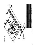
Page 64: ...PRARM50298 LH ACC Arm Rocker Spring LH 7 1 FASBL 0822 M8 x 20 Hex Head Set Screw 8 2 FASBL 0601 M6 x 16 CL100 HT HEX S L Z P 9 1 FASBL 0830 M8 x 30 Socket Head Dome 10 1 FASCC 1001 M10 External Circlip 11 1 FASGS 0501 M5 x 6mm Cup Point Grub Screw DIN 914 12 2 FASNT 0802 M8 Half Nut 13 2 FASWA 0803 M8 Internal Star Washer 14 3 FASWA 1091 M10 Nylon Washer Form A 1 11 10 3 5 7 4 8 14 1 2 13 12 9 6 P...

Page 65: ...0813 M8 x 10 Hex Head Set Screw 13 2 FASBL 9612 M6 x 10 Socket Flange Head Set A2 14 1 FASCC 1001 M10 External Circlip 15 1 FASGS 0501 M5 x 6mm Cup Point Grub Screw DIN 914 16 1 FASNT 0802 M8 Half Nut 17 2 FASWA 0803 M8 Internal Star Washer 3 FASWA 1091 M10 Nylon Washer Form A 1 11 12 9 4 16 8 3 14 13 2 6 15 7 10 5 Press Fit Secure Cable Ties Around Hoses Contact PLS Contact PLS 8 17 1 M E A S U R...

Page 66: ...BARM50267 ACC Arm Cylinder Pin 6 1 FASCC 1201 M12 External Circlip 7 1 FASGS 0501 M5 x 6mm Cup Point Grub Screw DIN 914 8 4 FASRV 0014 4 8 x 16 Large Flange Head Rivet 9 1 ACCPRISREFYELTAPE Y YELLOW REFLECTIVE PRISMATIC TAPE 50 x 50 x 50m 9 Contact PLS M E A S U R E L E N G T H B E F O R E C O N T A C T I N G P L S M E A S U R E L E N G T H B E F O R E C O N T A C T I N G P L S Note Fixings may va...

Page 67: ...Pin 6 1 FASCC 1201 M12 External Circlip 7 1 FASGS 0501 M5 x 6mm Cup Point Grub Screw DIN 914 8 4 FASRV 0014 4 8 x 16 Large Flange Head Rivet 9 1 ACCPRISREFYELTAPE Y YELLOW REFLECTIVE PRISMATIC TAPE 50 x 50 x 50m 1 6 Contact PLS M E A S U R E L E N G T H B E F O R E C O N T A C T I N G P L S M E A S U R E L E N G T H B E F O R E C O N T A C T I N G P L S 3 8 4 7 5 2 PRESS FIT 9 Note Fixings may var...

Page 68: ... Cylinder Mega 1 4 2 FASNT 1603 M16 Half Nut 5 2 HYDFT 0004 1 4 BSP Male Male Straight 6 4 HYDWA 0001 1 4 BSP Dowty Seal Bonded Washer 7 2 Contact PLS 8962 Cylinder Spacer 8 1 ACC27119 PC Valves 100420 Crash Valve New Type Pair SUPPLIED IN PAIRS MUST BE CHANGED IN PAIRS 5 2 3 4 6 8 7 6 Note Fixings may vary Arm Cylinders 20 ...

Page 69: ...y vary Arm Brace 1 2 PARTS LIST ITEM QTY PART NUMBER DESCRIPTION 1 1 Contact PLS ACC Arm Stabilizer 2 6 FASBL 0624 M6 x 20 Socket Flange Dome Head A2 M E A S U R E L E N G T H B E F O R E C O N T A C T I N G P L S 21 ...

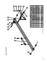
Page 70: ...l 5 1 FASBL 1005 Socket Capscrew M10 x 60 BZP 6 1 FASNT 1001 M10 Nyloc Nut 7 1 ACCFABBRP50530 22 ACC Bridge Plate Roller 22 8 2 ACC Bridge Plate Torsion Bar 4 2 5 7 6 8 Contact PLS Contact PLS M E A S U R E L E N G T H B E F O R E C O N T A C T I N G P L S M E A S U R E L E N G T H B E F O R E C O N T A C T I N G P L S M E A S U R E L E N G T H B E F O R E C O N T A C T I N G P L S 3 1 Note Fixing...

Page 71: ...late Folded Ally 2 3 HASCL 0740 Black Cleating 75 x 740mm 3 1 470 m HASCL 0002 50mm Yellow Cleating Roll 18 3m M E A S U R E L E N G T H B E F O R E C O N T A C T I N G P L S W I D T H M E A S U R E B E F O R E C O N T A C T I N G P L S Note Fixings may vary Bridge Plate Alloy 23 ...

Page 72: ...BARM50266 ACC Arm Pin Plain 5 2 ACCFABBRP50538 ACC Bridge Plate Hinge Plate Pivot 6 1 ACCFABBRP50539 LH ACC Bridge Plate Adjuster Cam LH 7 1 ACCFABPLA50356 ACC Platform Swivel Joint 8 2 ACCFABPLA50370 ACC Crank Pivot Plate 9 4 ACCFABPLA50371 ACC Crank Pivot Plate Spacer 10 1 Contact PLS ACC Platform Lite H 11 1 ACCFABPLA50336 ACC Platform Double Collar 12 1 ACCFABPLA50366 ACC Platform Single Colla...

Page 73: ...m Yellow Cleating Roll 18 3m 4 8 HASCL 0740 Black Cleating 75 x 740mm 5 1 000 m PACTP 0001 25 mm Double Sided Tape Glue 2 1 3 4 5 M E A S U R E W I D T H B E F O R E C O N T A C T I N G P L S M E A S U R E L E N G T H B E F O R E C O N T A C T I N G P L S NOTES Ensure Surface Is Correctly Prepared And Cleaned Note Fixings may vary Platform Alloy 25 ...

Page 74: ...form Extension Stop Mild Steel 25mm 7 2 FASBL 0804 M8 x 16 CL 100 HT HEX S L Z P 8 1 FASBL 0805 M8 x 25 CL100 HT HEX S L Z P 9 1 FASBL 0806 M8 x 35 Socket Head CSK 10 2 FASBL 0823 M8 x 20 Socket Head CSK 11 2 FASOL 1230 M12 x 30 S Steel Socket Set 12 2 FASNT 1003 M10 Half Nut 13 1 FASNT 1603 M16 Half Nut 14 2 FASWA 1003 M10 Internal Star Washer 15 1 FASWA 1603 M16 Internal Star Washer M E A S U R ...

Page 75: ... 3m Black 5 8 FASBL 9611 M6 x 8 Socket Large Flange Head Set A2 6 1 400 m HASCL 0002 50mm Yellow Cleating Roll 18 3m 7 7 HASCL 0740 Black Cleating 75 x 740mm 2 Contact PLS Contact PLS M E A S U R E W I D T H B E F O R E C O N T A C T I N G P L S M E A S U R E L E N G T H B E F O R E C O N T A C T I N G P L S NOTES Ensure Surface Is Correctly Prepared And Cleaned Note Fixings may vary Extension All...

Page 76: ...PARTS LIST ITEM QTY PART NUMBER DESCRIPTION 1 1 ACC26199 T 10 x 1 5 x 395mm Extension Tube 2 1 ACCHYDHOS530 005 885 ACC Extension Pipe Hose 885 2 1 Note Fixings may vary Extension Pipe and Hose 28 ...

Page 77: ...xtruded Ramp 2015 6 1 ACC Extruded Ramp 2015 7 2 ACCPRISREFREDTAPE R RED REFLECTIVE PRISMATIC TAPE 50 x 50 x 50m 8 2 CONEC 0001 Handrail Rubber Stop 9 1 CONLB 0014 Access Ramp Sticker PLS314 10 0 005 l ADTHR 0001 A1042 Threadlock Adhesive Permabond 50ml 11 6 FASSC 9001 6 3 x 25mm A2 Socket Cap Head Self Tapper per 100 12 4 FASRV 0001 4 8 x 16 Dome Head Rivet 13 6 FASWA 0603 M6 Internal Star Washer...

Page 78: ...losed Pack 12V 24V 4 10 000 g CONOT 0014 500g Petroleum Jelly 5 2 FASBL 1029 M10 x 60 Hex Head Set Screw 6 2 FASNT 1001 M10 Nyloc Nut 7 4 FASWA 1001 M10 Plain Washer Form A 9 1 CONLB 0020 AF26 Alu Foil w on Labels Serial No Pack 350 10 1 CONLB 0002 WL28 LABEL LEGEND TESTED PACK 350 11 1 CONLB 0003 This Way Up PLS Blue Sticker 12 1 ACC26469 Vinyl Round PLS Label Note Fixings may vary External Enclo...

Page 79: ...roleum Jelly 5 2 FASBL 1029 M10 x 60 Hex Head Set Screw 6 2 FASNT 1001 M10 Nyloc Nut 7 4 FASWA 1001 M10 Plain Washer Form A 9 1 CONLB 0020 AF26 Alu Foil w on Labels Serial No Pack 350 10 1 CONLB 0002 WL28 LABEL LEGEND TESTED PACK 350 11 1 CONLB 0003 This Way Up PLS Blue Sticker 12 1 ACC26469 Vinyl Round PLS Label 3 6 7 5 1 2 10 11 9 12 Notes Oil Supplied Separately Note Fixings may vary Internal E...

Page 80: ...S LIST ITEM QTY PART NUMBER DESCRIPTION 1 1 2 1 ACCHSET15035 01 Handset Unit 2 Button 1mm 2 1 2 3 3 1 ACC25631 Holster ACCALYHAN50735 ACC Standard Handset Hook Note Fixings may vary Standard Handset Kit 32 ...

Page 81: ...1 2 PARTS LIST ITEM QTY PART NUMBER DESCRIPTION 1 2 2 ACCALYHAN50735 ACC Standard Handset Hook ELEHA 0004 2 Button Single Handset Plug Kit 1 3 1 ACC25631 Holster 3 Note Fixings may vary Handset Kit 33 ...

Page 82: ...15 Notes ...

Page 83: ...15 Notes ...

Page 84: ...ervices Limited Unit 2 Summit Crescent Ind Est Off Roebuck Lane Smethwick West Midlands B66 1BT U K Tel 44 0 121 552 0660 Fax 44 0 121 552 0200 E mail enquiries pls access co uk Web Site www passengerliftservices co uk ...

Reviews: