background image


273


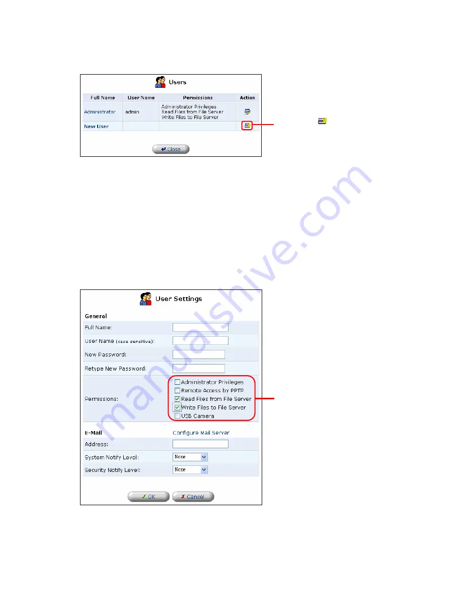
4. The [User Settings] window will be displayed.  Enter [Full Name], [User Name] and 

[New Password].   


Caution:


If the OS of the user is Windows ®, enter the same Windows ® login name and login 

password already used by the user.     


5. In the [Permissions] section, select the access permissions to the file server.   


Click on the 

 button 

Select 

Summary of Contents for BRC-14VG

Page 1: ...4 Port VPN Virtual Private Network Broadband Router BRC 14VG ...

Page 2: ...he update file of the internal system software firmware is performed as needed as a part of our customer service We do not guarantee on the contents of update or its schedule Generally a separate contract with an Internet service provider is required to use public networks including the Internet Some ISP s may restrict the number of terminals computers that can be connected to the public network o...

Page 3: ...e to sunlight or locations near heat radiators Overheating of the product may result in electric shock or fire or it may cause the product to malfunction or fail Avoid severe temperature change Even the temperature is within the operating temperate ranges for the product severe change in temperature may result in condensation that in turn causes electric shock fire product malfunctioning or failur...

Page 4: ...tered trademarks of Microsoft Corporation of America in the U S A or in other nations The official name of Windows is Microsoft Windows Operating System Windows XP is an abbreviation of Microsoft Windows XP Home Edition operating system and Microsoft Windows XP Professional operating system Windows 2000 is an abbreviation of Microsoft Windows 2000 Professional operating system Windows Me is an abb...

Page 5: ... IP Masquerading 33 4 3 DHCP Server Configuration 34 4 3 1 Basic configuration of DHCP server 34 4 3 2 Assigning a static IP address via DHCP server 37 4 3 3 Changing IP Address 39 4 3 4 Deleting IP Address 41 4 3 5 Enabling and disabling DHCP server 43 4 4 DNS Server Configuration 46 4 4 1 Verifying host name and IP address via DHCP server 46 4 4 2 Manual registration of host name and IP address ...

Page 6: ...Syslog Configuration 127 Chapter 6 Making LAN side PC s publicly accessible 130 6 1 Local Server Configuration 130 6 1 1 Local Server Configuration 130 6 1 2 Configuring a Local Server Using a New Service 133 6 1 3 Modifying Local Server Configuration 143 6 1 4 Enabling Disabling Local Server 145 6 1 5 Deleting Local Server 147 6 2 DMZ Configuration 149 6 2 1 Configuring a LAN Side PC as Virtual C...

Page 7: ...nfiguring USB Camera 197 9 1 2 Viewing the Captured Images via the Internet 199 9 1 3 Viewing captured images from a PC or cellular phone 201 Chapter 10 Maintenance and administration 205 10 1 Verifying Device Status 205 10 1 1 Verifying Connection Status 205 10 1 2 Verifying System Up Time 206 10 2 Configuring Login User Name and Password 208 10 2 1 Configuring Login User Name and Login Password ...

Page 8: ...tition 247 11 1 5 Attaching a Formatted USB Storage Device 258 11 1 6 Deleting an Existing Partition 263 11 1 7 Removing the Hard Disk 266 11 2 Access Configuration 269 11 2 1 Configuring a Workgroup 269 11 2 2 Creating a User Account 271 11 2 3 Accessing the File Server 274 11 3 Configuring a Web Server 293 11 3 1 Remote Access Configuration 293 Chapter 12 Printer Server 296 12 1 Printer Server S...

Page 9: ...eed than conventional routers Its VPN gateway achieves robust network security while the product allows you to establish various network resources including i Network Attached Storage NAS that utilizes a separate USB storage and ii a simple real time image distribution system that uses an option USB camera Caution Either the use of a VPN router like the BRC 14VG or access from multiple PC s may be...

Page 10: ...vity ISP priority can be manually adjusted The product supports up to four simultaneous sessions connections zUnnumbered multiple global IP address function The product supports multiple global IP address service offered by your ISP and let i global IP address host and ii private address host coexist on the LAN side of the router Furthermore the BRC 14VG allows private address host to communicate ...

Page 11: ...n this log and data transmitted from the WAN side Should it detect any contradiction it will block the packets in question to protect the network from unauthorized packets or attacks zSecurity Level The 3 level security system of the product allows you to easily set up security function The configuration can be customized as needed to let you flexibly configure LAN to Internet as well as Internet ...

Page 12: ...l Server function is enabled access packets from the WAN side are transferred to a designated PC on the LAN side zVirtual Computer This feature allows a PC on the LAN side to be publicly accessible from the WAN side Virtual Computer is useful especially when the port information required to use Local Server is not available or when you wish all services to be provided by a single publicly accessib...

Page 13: ...roduct package contains all of the following parts zBRC 14VG zQuick Installation Guide zCD ROM User s Manual zAC Adapter zUTP Straight through LAN Cable 1m zWarranty Card Please contact our technical support if any of the above components is missing ...

Page 14: ...ff There is a 100M link on LAN port There is a 10M link on LAN port Link Act LED Green On Off Active connection on LAN port Data is being sent received on LAN port WAN LED Green Off On Flashing No connection on LAN port Active connection on WAN port Data is being sent received on WAN port PPPoE LED Green Off On Flashing No connection on WAN port Active PPPoE connection on WAN port No PPPoE connect...

Page 15: ...15 Rear View Back View WAN WAN side MAC address LAN LAN side MAC address WAN Port USB Port LAN Port Reset Switch Power ON OFF DC Power Jack ...

Page 16: ...uipment A twisted pair cable x n n the number of computers attached to the product About Web Configuration Screen The system configuration of the product is adjusted via a Web browser Please make sure that 1 a Web browser has been already installed on your computer and 2 JavaScript is enabled on that browser Windows and MacOS Microsoft Internet Explorer 5 0 or greater Netscape Navigator 6 0 or gre...

Page 17: ...itialization will be deleted zIt is highly recommended to remove all the network cables attached to the product from the router before initializing its configuration zPlease do not remove the AC power adapter from the product until the initialization process is complete Initialization Procedure 1 Remove the AC power adapter from the product 2 Press and hold down the reset switch then attach the AC...

Page 18: ...elect a suitable place on the network to install the BRC 14VG Ensure the BRC 14VG and the DSL Cable modem are powered OFF 3 Connect LAN Cables Use standard LAN cable to connect PCs to the switching hub ports on the BRC 14VG Both 10BaseT and 100BaseT connections can be used simultaneously If required connect any port to a normal port on another hub using a standard LAN cable Any LAN port on the BRC...

Page 19: ...Use the cable supplied with your DSL Cable modem If no cable was supplied use a standard cable 5 Power Up Power on the Cable or DSL modem Connect the supplied AC power adapter to the BRC 14VG and power up Use only the power adapter provided Using a different one may cause hardware damage ...

Page 20: ...tp 192 168 1 1 in the address field 2 The first time Login Setup screen will be displayed Specify the login user name and login password to access the management console Once the user name and password have been configured Login screen will be displayed instead 1 User Name Enter a user name 1 to 64 alphanumeric characters Enter http 192 168 1 1 Enter user name and password ...

Page 21: ... new password 1 to 64 alphanumeric characters The characters entered in this field will be displayed as 3 Retype new password Enter the same password for verification 3 Click OK 4 The management console will be displayed Click ...

Page 22: ...22 5 Click on Connection Wizard icon on the left side of the screen 6 After steps of configure depends on your ISP Click ...

Page 23: ...23 3 2 For Cable Modem 1 Select Internet Connection and click Next 2 Select Ethernet Connection and click Next Select Click Select Click ...

Page 24: ...ynamic Negotiation DHCP and click Next 4 Connection Summary screen will be displayed Verify the new settings and click Finish The product will now automatically obtain an IP address from your ISP Select Click Click ...

Page 25: ...25 3 3 For ADSL Static IP 1 Select Internet Connection and click Next 2 Select Ethernet Connection and click Next Select Click Select Click ...

Page 26: ...k Next 4 Manual IP Address configuration page will be displayed Refer to the information provided by your ISP and enter IP Address Subnet Mask Default Gateway Primary DNS Server and Secondary DNS Server addresses Click Next Select Click Enter data Click ...

Page 27: ...27 5 Connection Summary screen will be displayed Verify the information displayed and click Finish Click ...

Page 28: ...28 3 4 For PPPoE 1 Select Internet Connection and click Next 2 Select External DSL Modem and click Next Select Click Select Click ...

Page 29: ...splayed Refer to the information provided by your ISP and enter the Login User Name and Login Password of the ISP Click Next 4 Connection Summary screen will be displayed Verify the information displayed and Click Finish Enter data Click Click ...

Page 30: ...alid IP address to the product Assigning an incorrect or invalid address to it may result in failure to connect to the Internet 4 1 1 Verifying and modifying LAN port IP address The factory default LAN port IP address of the product is 192 168 1 1 Follow the steps below tf you need to assign another IP address to the LAN port ex the product is installed in an existing LAN etc 1 Click on Network Co...

Page 31: ...ings 4 The LAN port IP address of the product is shown in the IP Address field To change IP address modify the displayed values as needed Network Connections page Click on the button LAN Ethernet Properties page Click ...

Page 32: ...he management console enter the new IP address to re enter the management console for further configuration Notes When changing LAN side IP address of the product After changing the IP address or subnet mask of the LAN side of the product be sure to adjust the DHCP server settings accordingly There is an active computer in the LAN If any of the PC s on your LAN is active while you change the IP ad...

Page 33: ...e private IP addresses assigned within a LAN are converted to one global IP address as a connection to the Internet is established Port numbers are converted as well From the Internet side it appears as if only one PC is connected to the Internet No special configuration is required to use NAPT This function is automatically enabled when the product is in use LAN LAN Cable LAN side IP address 192 ...

Page 34: ...n The DHCP server function of the product is enabled by default If you do not wish to use the DHCP server function manually assign an IP address to each PC attached to your LAN When IP is manually configured to each PC its host name and IP address cannot be managed by the product 4 3 1 Basic configuration of DHCP server This section describes the basic configuration of DHCP server settings LAN LAN...

Page 35: ...e Advanced icon on the side bar 2 Click on the IP Address Distribution icon 3 The subnet and dynamic IP range of DHCP server will be displayed To modify any of the values click on the button Click Click Advanced window ...

Page 36: ...Subnet Mask Enter the subnet mask to be assigned Least Time in Minutes Enter the expiration period of IP address in minutes Provide Host Name If Not Specified by Client Host name is automatically assigned if no host name has been assigned to the PC or network device attached 5 Click OK IP Address Distribution window will be displayed again 6 The DHCP server function setup is now complete IP Addres...

Page 37: ...s section provides the procedure to configure the DHCP server function to always assign a static IP address to a specific PC or network device 1 Click on the Advanced icon on the side bar 2 Click on the IP Address Distribution icon Click Click Advanced window ...

Page 38: ... add then click OK Host Name Enter the host name of the PC or network device to add 1 63 alphanumeric characters IP Address Enter the IP address you wish to assign to the new PC or network device MAC Address Enter the MAC address of the PC or network device to which an IP address is assigned IP Address Distribution window Click DHCP Connections window Click Enter values Click ...

Page 39: ...on setup is now complete 4 3 3 Changing IP Address This section describes the procedure to change the configuration of PC or network device to which IP address is automatically assigned via DHCP server 1 Click on the Advanced icon on the side bar 2 Click on IP Address Distribution icon Verify Click ...

Page 40: ...button 4 Click on the button for the host entry for which you wish to change configuration 5 Select Static Lease Type and click on OK Click Advanced window IP Address Distribution window Click DHCP Connections window Click on the button ...

Page 41: ...tic IP or modify host name and MAC address settings 8 Click on the OK button DHCP Connections window will be displayed again 9 The IP setup is now complete 4 3 4 Deleting IP Address This section describes how to delete a registered IP address and host associated with the Select Click Verify Click on the button ...

Page 42: ...42 address 1 Click on Advanced on the side bar 2 Click on IP Address Distribution 3 Click on the Connection List button Click Click Advanced window ...

Page 43: ... window will be displayed again 6 The IP deletion is now complete 4 3 5 Enabling and disabling DHCP server The section below describes how to enable or disable the built in DHCP server function 1 Click on Advanced on the side bar IP Address Distribution window Click DHCP Connections window Click on the button ...

Page 44: ...ick on IP Address Distribution 3 The current DHCP server subnet and the range of IP addresses being assigned will be displayed Click on the button to modify the DHCP server settings Click Click Advanced window ...

Page 45: ...k device attached to the LAN side of the product 5 Click OK The IP Address Distribution window will be displayed again Should you see a warning window after clicking on the OK button verify the displayed information and click OK to return to the IP Address Distribution window 6 The DHCP server configuration is now complete IP Address Distribution window Click on the button DHCP Settings for LAN Et...

Page 46: ...S server of the product only manages the association between IP address and domain name within LAN In connection that specifies a domain name on the Internet the Proxy DNS function of the product is used 4 4 1 Verifying host name and IP address via DHCP server The built in DNS server of the product refers to the same association table used by DHCP server DNS server thus reflects host names and IP ...

Page 47: ...47 2 Click IP Address Distribution 3 Click on the Connection List button Click Click Advanced window ...

Page 48: ... registered 5 Click on the Close button to return to the IP Address Distribution window 6 Click on the Close button to return to the Advanced window 7 Click on the DNS Server icon IP Address Distribution window Click DHCP Connections window Host name and IP address will be displayed ...

Page 49: ...ion of IP and host name is now complete 4 4 2 Manual registration of host name and IP address When DHCP server function is not in use host name and IP address need to be registered manually 1 Click on the Advanced icon on the side bar Click Advanced window DNS Server window Host name and IP address will be displayed ...

Page 50: ...50 2 Click on the DNS Server icon 3 Click on the button in the New DNS Entry field Click Click Advanced window ...

Page 51: ...er changing host name or IP address the information previously registered to DNS server needs to be manually modified as well Caution If DHCP server function is enabled DNS server will automatically reflect changes made to PC host names There is not need to manually change host names 1 Click on the Advanced icon on the side bar DNS Server window Click on the button DNS Entry window Enter data Clic...

Page 52: ...52 2 Click on the DNS Server icon 3 Click on the button for the host name you wish to modify Click Click Advanced window ...

Page 53: ...ly their host name may be changed 5 The manual configuration of host name and IP address is now complete 4 4 4 Deleting host name and IP address Follow the steps below to delete previously registered host name or IP address 1 Click on the Advanced icon on the side bar DNS Server window Click on the button DNS Entry window Make change Click ...

Page 54: ...54 2 Click on the DNS Server icon 3 Click on the button for the host name you wish to delete then click OK Click Click Advanced window ...

Page 55: ...55 4 The deletion of host name or IP address is now complete DNS Server window Click on the button Click ...

Page 56: ... it is serving as a DNS server that manages the domain on the Internet to IP address association If there are multiple online sessions on the WAN side upon reception of DNS inquiry from LAN side PC the built in proxy DNS of the product will send inquiry packet to DNS server on all of the active sessions In this case data communication takes place using a session whose DNS server responded If DNS s...

Page 57: ...ing information Specify an interface on which dynamic routing is enabled then enable dynamic routing on the product 1 Click on the Network Connections icon on the side bar 2 Click on the button for the interface for which you wish to enable dynamic routing 3 In this section LAN Ethernet is selected as an example If you wish to select another interface choose the interface and follow the steps belo...

Page 58: ...P the product receives in the Listen to RIP Messages field Similarly select the type of RIP that the product transmits in the in the Send RIP Messages field RIP receive configuration None Disables the RIP function RIPv1 Receives routing information via RIPv1 RIPv2 Receives routing information via RIPv2 RIPv1 2 Receives routing information via RIPv1 2 RIP send configuration LAN Ethernet Properties ...

Page 59: ...rmation via RIPv2 RIPv2 multicast Sends routing information via RIPv2 7 Click OK If a warning window appears verify the displayed information and click on the OK button 8 LAN Ethernet Properties window will be displayed again 9 Click on the Advanced icon on the side bar 10 Click on the Routing icon Click Click ...

Page 60: ...ocols section 12 Click on the OK button 13 The dynamic routing configuration is now complete 4 6 2 Adding static routing information This section describes how to manually add routing information 1 Click on the Advanced icon on the side bar Click Advanced window Routing window Make change ...

Page 61: ...61 2 Click on the Routing icon 3 Click on the button in the New Route field Click Click Advanced window ...

Page 62: ...er the network address of packet destination Netmask Enter the netmask of packet destination Gateway Enter the address of the first gateway through which the target network is reached Metric Enter the hop count the number of gateways used between the product and target network 5 Click OK The routing information entered in Step 4 will be added to the Routing Protocols section Click on the button Ro...

Page 63: ...mation is now complete 4 6 3 Modifying static routing information This section describes how to modify previously configured static routing information 1 Click on the Advanced icon on the side bar 2 Click on the Routing icon Verify Click Click ...

Page 64: ...64 3 Click on the button for the routing information you wish to modify 4 Modify the routing information selected and click on the OK button Click Advanced window Click on the button Routing window ...

Page 65: ...is now complete 4 6 4 Deleting static routing information This section describes how to delete previously configured static routing information 1 Click on the Advanced icon on the side bar 2 Click on the Routing icon Routing Settings window Modify Click Click ...

Page 66: ...3 Click on the button for the routing information you wish to delete 4 Click on the OK button 5 The deletion of routing information is now complete Click Advanced window Click on the button Routing window ...

Page 67: ...indows ME can detect the product The status of the product can be monitored via UPnP compliant OSes Windows XP and Windows ME and some of its parameters are also configurable through these OSes PC s within the LAN attached to the product may access UPnP ready applications such as Windows Messenger and MSN Messenger Note that Windows 98 Windows 2000 and Macintosh do not support UPnP The UPnP functi...

Page 68: ... 2 Click on the Add or Remove Programs button then click on Add Remove Windows Components button on the left 3 Select Networking Services in the Components list and click on the Details button Click Click ...

Page 69: ...l Plug and Play has been already checked UPnP has already been enabled on your PC Close the dialog box If the item is not checked UPnP is disabled at the moment Check select the item and click OK then follow the displayed instructions to continue the installation 5 The UPnP setup is now complete Verify Select Click ...

Page 70: ...70 Windows Me 1 Click on the Start button then click Settings Control Panel 2 Click on the Add Remove Programs button When the Add Remove Programs window is displayed click on the Windows Setup tab ...

Page 71: ...71 3 Select Communications in the Components list and click on the Details button Click ...

Page 72: ...72 4 The details of communication status will be displayed Verify the status of Universal Plug and Play Select Click ...

Page 73: ...ox If the item is not checked UPnP is currently disabled Check select the item and click OK Follow the displayed instructions to continue the installation process 6 UPnP setup is now complete 4 7 2 Disabling UPnP Follow the steps below to disable the UPnP function of the product 1 Click on the Advanced icon on the side bar Verify ...

Page 74: ...74 2 Click on the Universal Plug and Play icon 3 To disable UPnP uncheck the check mark in the Allow other network box Click Click Advanced window ...

Page 75: ...75 4 Click on the OK button 5 UPnP has been disabled on the product Uncheck Universal Plug and Play window ...

Page 76: ... product utilizes Stateful Packet Inspection as its firewall technology Packet consistency is checked per communication session to open only the required ports Ports in use are blocked as soon as communication is over Furthermore the technology detects DoS Denial of Services attacks from the Internet to block unauthorized access from the outside ALG Application Level Gateway Packets are allowed or...

Page 77: ...itted while Internet to LAN access is denied The security function of the product provides three security levels by default The security configuration can be customized to meet your specific needs and objectives 1 Click on the Security icon on the side bar 2 Change the level selection as necessary Security Level Connection request from the Internet Connection request from the PC s in LAN Maximum D...

Page 78: ...ay use all Internet services When Maximum Security is selected the following Internet services are accessible from the PC s in LAN Telnet FTP HTTP HTTPS DNS IMAP POP3 SMTP Caution Minimum Security level will disable all the security functions of the product Select this level only when it is necessary 3 Check Block IP fragments This option allows the product to block attacks that use fragmented dat...

Page 79: ...AN Ethernet rule and WAN PPPoE rule 5 3 1 Configuring Packet Filter This section describes how to set up a packet filter to the product Creating a Packet Filter 1 Click on the Security icon on the side bar Rule Application Order Rule Application Order LAN Ethernet Rule WAN Ethernet Rule WAN PPPoE Rule VPN PPTP Rule VPN IPSec Rule Receive Send LAN Ethernet Rule WAN Ethernet Rule WAN PPPoE Rule VPN ...

Page 80: ...80 2 Click on the Advanced Filtering tab 3 The following tables will be displayed Click Security window Click ...

Page 81: ...e selected another interface configure it in the similar manner Rules available on the product LAN Ethernet Rules Rules applied to LAN ports WAN Ethernet Rules Rules applied to WAN port WAN PPPoE Rules Rules applied to WAN PPPoE port VPN PPTP Rules Rules applied to VPN PPTP connection VPN IPSec Rules Rules applied to VPN IPSec connection WAN selected as an example ...

Page 82: ...dow will be displayed 7 Enter the Source and Destination IP addresses in the Matching field When Any is selected the rule is applied to all IP addresses When Single is selected the rule is applied only the IP address entered Click on the button Configure WAN Ethernet Rules window Add Advanced Filter window Select Enter address ...

Page 83: ...r Accept Accept all packets related to this session This session is handled by Stateful Packet Inspection SPI Accept Packet Accept packets matching this rule only Do not use Stateful Packet Inspection SPI to also automatically accept packets related to this session 9 The Service Name section will list the services and applications already registered to the product Select the service to which the f...

Page 84: ...own at the bottom of the window Scroll down as necessary 11 Repeat Steps 3 to 10 for any additional filter rule you wish to create 12 Filter rule setup is now complete Modifying Packet Filter 1 Click on the Security icon on the side bar Select Click ...

Page 85: ...85 2 Click on the Advanced Filtering tab 3 Click on the button of the interface you wish to configure Click Security window Click ...

Page 86: ...ld 5 Edit Advanced Filter window will be displayed Make changes as necessary and click on the OK button The OK button is shown at the bottom of the window Scroll down as necessary WAN selected as an example Configure WAN Ethernet Rules window Click on the button Edit Advanced Filter window Modify ...

Page 87: ...87 6 The rule you have selected has been modified Deleting Packet Filter 1 Click on the Security icon on the side bar 2 Click on the Advanced Filtering tab Click ...

Page 88: ...3 Click on the interface for which you wish to delete a rule 4 Configure WAN Ethernet Rules window will be displayed Click on the button in the Action field Security window Click WAN selected as an example ...

Page 89: ...igure a service that has not been registered to the product 1 In the Add Advanced Filter window click on the User Defined Services link 2 User Defined Services window will be displayed Click on the button in the New Entry field Configure WAN Ethernet Rules window Click on the button Click Add Advanced Filter window ...

Page 90: ...s Destination Ports Enter the port number of the source destination port of the service or application Any Specifies all ports Single Specifies one port number Range Specifies the range of port numbers ICMP Message Select the target ICMP message 5 Click on the OK button 6 To configure multiple ports click on the button User Defined Services window Click on the button Edit Service window Click on t...

Page 91: ... click OK 8 The User Defined Serviced window will be displayed again Verify that the service you have configured is listed in the Service Name section Click on the Close button 9 The new service will be listed under the User Defined Services section Click on the button Verify Click Service is added ...

Page 92: ... LAN occasionally result in unexpected communication to the Internet Blocking ports 137 139 used by NetBIOS prevents the occurrence of such unexpected communication Direction Operation Protocol Source IP Address Destination IP Address Source Ports Destination Ports LAN Ethernet Receive Drop TCP UDP Any Any Any 137 139 Send WAN Ethernet Drop TCP UDP Any Any Any 137 139 1 Click on the Security icon ...

Page 93: ...le a rule for blocking LAN to WAN NetBIOS packets is created In the Input Rule Sets field click on the button for LAN Ethernet Rules 4 Click on the button in the New Entry field Security window Click Click on the button ...

Page 94: ...or both Source IP Address and Destination IP Address 6 Select Drop in the Operation field 7 Click on User Defined Services Click on the button Configure LAN Ethernet Rules window Select Add Advanced Filter window Select ...

Page 95: ...e window will be displayed Click on the button in the New Entry field 10 Select TCP as protocol Next select Any as Source Ports and select Range as Destination Ports Enter 137 and 139 as range Click Add Advanced Filter window User Defined Services window Click on the button Edit Service window Click on the button ...

Page 96: ...otocol Next select Any as Source Ports and select Range as Destination Ports Enter 137 and 139 as range 14 Click on the OK button 15 Edit Service window will be displayed Enter the name of new service in the Service Name field and click OK Configure parameters Click on the button Configure parameters ...

Page 97: ...ayed again Verify that the service you have created is listed under Service Name Click on the Close button 17 The new service is listed under User Defined Services Select check the service and click on the OK button Enter service name Click Click Select ...

Page 98: ...utton 20 Follow the steps below to configure output packets In the Output Rule Sets section click on the button for WAN Ethernet Rules 21 Click on the button in the New Entry field 22 Select Any as both Source IP Addresses and Destination IP Addresses Click Configure LAN Ethernet Rules window Click on the button Click on the button Configure WAN Ethernet Rules window ...

Page 99: ...99 23 Select Drop in the Operation section 22 The new service will be displayed in the User Defined Rules section Select this entry and click on the OK button Select Add Advanced Filter window Select ...

Page 100: ...ayed at the bottom of the window Scroll down as necessary 23 Click on the OK button to return to the Advanced Filtering window 24 The configuration of sample rule is now complete Select Click Configure WAN Ethernet Rules window ...

Page 101: ...on To prevent unauthorized access and modification of the system by third parties it is recommended to disable remote access for normal use Enable this function only when it is needed The remote access function configured on the product will be given priority over Local Server and Virtual Computer 5 4 1 Configuring Remote Access 1 Click on the Security icon on the side bar 2 Click on the Remote Ad...

Page 102: ...the Well Known HTTP Port 80 Select if you wish to make the HTTP port of the product publicly accessible Allow Incoming Access to the Web Management Using Secondary HTTP Port Select to make the product s Security window Click Select as necessary Click ...

Page 103: ...ow Incoming UDP Traceroute Queries Select if you wish to verify the route on UDP via the traceroute command Option Settings Select to allow incoming access to USB camera Caution If you wish to use the Traceroute command via Windows to trace route select Allow Incoming ICMP Echo Requests e g pings and ICMP traceroute queries To access the web management console from the WAN side enter the following...

Page 104: ... site For instance Web sites that may offend public order and morals may be configured on the product to prevent LAN side PC s to view such sites 5 5 1 Configuring URL Filter Creating a New URL Filter 1 Click on the Security icon on the side bar 2 Click on the IP Hostname Filtering tab Click ...

Page 105: ...105 3 Click on the button in the New Entry field 4 Enter the URL or IP address of the Web site you wish to block access to and click on OK Security window Click Click on the button Click ...

Page 106: ...ether the URL exists on the Internet During the process the Status is displayed as Resolving Click on the Refresh button to verify that the URL entered is valid 7 Click on the OK button to enable the new configuration 8 The addition of restricted site is now complete Restricted Web Site Address window Enter address Verify Click ...

Page 107: ...the URL to see whether the Web site is displayed If the site is accessible there is a chance that the URL entered on the product was inaccurate Enabling Disabling URL Filter 1 Click on the Security icon on the side bar 2 Click on the IP Hostname Filtering tab Click ...

Page 108: ... to disable URL filter then click OK 4 The screen will get back to the homepage Please get back to IP Hostname Filtering tab and confirm again 5 Status will change from Resolved to Disabled To enable URL filter on the site select check the URL entry again Security window Click Click Uncheck ...

Page 109: ...109 6 The URL filter has been disabled enabled Modifying a URL filter 1 Click on the Security icon on the side bar 2 Click on the IP Hostname Filtering tab Verify Click ...

Page 110: ...0 3 Click on the button of the Web site entry you wish to configure 4 When the Restricted Web Site Address is displayed enter a new URL or IP address and click OK Security window Click Click on the button ...

Page 111: ...he new Web site is added to the Web Site Address list 6 The URL filter has been modified Deleting a URL filter 1 Click on the Security icon on the side bar Restricted IP Address or Hostname window Click Verify ...

Page 112: ...112 2 Click on the IP Hostname Filtering tab 3 Click on the button of the Web site entry for which you wish to remove access restrictions Click Security window Click ...

Page 113: ...113 4 Click on the OK button 5 The deletion of URL filter is now complete Click on the button ...

Page 114: ...n describes how to configure access log of LAN PC to Internet Internet to LAN and management console connections 5 6 1 Verifying Security Log Viewing Log 1 Click on the Security icon on the side bar 2 Click on the Security Log tab Click ...

Page 115: ...115 3 The Security Log window will be displayed You can view the log related to the currently active security settings Security window Click Log information ...

Page 116: ...all security policy Blocked IP Fragment After the firewall has been configured to block all IP fragments an IP fragment was blocked Error is displayed for each fragment blocked Blocked IP Source Routes Packets are blocked because source route control option is enabled on the IP header Inbound Outbound Traffic Blocked State table error Error occurred while the firewall was examining or operating on...

Page 117: ...117 Clearing Log 1 Click on the Security icon on the side bar 2 Click on the Security Log tab Click Security window Click ...

Page 118: ... log currently shown on screen 4 Click on the Close button 5 The system log has been cleared Detailed Configuration of Log This section describes how to modify the configuration for saving log 1 Click on the Security icon on the side bar Click Click ...

Page 119: ...119 2 Click on the Security Log tab 3 Click on the Settings button Security window Click Click ...

Page 120: ...e saved as log Spoofed Connection Attempts LAN to Internet and Internet to LAN connections whose source IP address have been spoofed and thereby denied by firewall are saved as log 5 In the Log Buffer section select the option to be used when log buffer is full Prevent Log Overrun Select this option to stop saving log when memory for saving log is full Uncheck this option to delete old log when me...

Page 121: ...121 5 7 E mail Notification The product can be configured notify its administrator of system line firewall error via e mail 1 Click on the Advanced icon on the side bar 2 Click on the Users icon Click ...

Page 122: ...122 3 Click on the button for the user to whom e mail notification is sent 4 Enter the destination mail address in the Address field see below Click Advanced window Click on the button Users window ...

Page 123: ...123 5 Select Security Notify Level System notification sends out messages related to system information Enter address User Settings window ...

Page 124: ...ning has occurred When this option is selected Error level message is sent as well Information The message displayed when the user uses the product is sent When this option is selected both Error and Warning level messages will be sent as well 6 Select Security Notify Level A message displayed in security log is sent out as security notification Select ...

Page 125: ...t as well Information The message displayed when the user uses the product is sent When this option is selected both Error and Warning level messages will be sent as well 7 Now configure the SMTP mail server for sending e mail from the product Click on the Configure Mail Server link 8 Enter the mail server address in the Outgoing Mail Server field and enter the source mail address in the From Mail...

Page 126: ...126 9 Click on the OK button to return to the User Settings window 10 Click on the OK button 11 The e mail notification setup is now complete Enter address ...

Page 127: ...og Configuration The product can be configured to send log to Syslog server when an error occurs to the system line or firewall 1 Click on the Advanced icon on the side bar 2 Click on the System Settings icon Click ...

Page 128: ...g has occurred When this option is selected Error level message is sent as well Information The message displayed when the user uses the product is sent When this option is selected both Error and Warning level messages will be sent as well 4 Locate the Security Remote Logging section Select the information to be notified via the Security Notify Level menu and enter the address of Syslog server in...

Page 129: ...r requiring warning has occurred When this option is selected Error level message is sent as well Information The message displayed when the user uses the product is sent When this option is selected both Error and Warning level messages will be sent as well 5 Click on the OK button 6 The Syslog configuration is now complete Enter address ...

Page 130: ... via the Internet and ii access applications including online games and chat programs Some services and applications used on the Internet have been already registered in the product to simplify Local Server configuration 6 1 1 Local Server Configuration This section provides a detailed procedure to configure local server 1 Click on the Security icon on the side bar LAN LAN Cable Internet Forwards ...

Page 131: ...131 2 Click on the Local Servers tab 3 Click on the button in the New Entry field Click Security window Click ...

Page 132: ...l server 5 Services and applications that have been already registered to the product will be listed in the Basic Web Utilities list Select the services you wish to make publicly accessible on the Internet or applications you wish to use 6 Click on the OK button Click on the button Add Local Server window Enter address Select ...

Page 133: ...ary 7 The local server configuration is complete 6 1 2 Configuring a Local Server Using a New Service Creating a New User Defined Service Follow the steps below to create a new service and use local server via the service 1 Click on the Security icon on the side bar Click Click ...

Page 134: ...134 2 Click on the Local Servers tab 3 Click on the button in the New Entry field 4 Register a new service Click on the User Defined Services link Security window Click Click on the button Click ...

Page 135: ...Select a protocol from among TCP UDP ICMP GRE ESP AH and Other When Other is selected manually specify the protocol number you wish to use Source Ports Destination Ports Enter the port number for the service or application Any Specifies all ports Single Specifies one port number Range Specifies the range of port numbers ICMP Message Select the target ICMP message 7 Click on the OK button Click on ...

Page 136: ...played again Verify that the new service created in the previous steps is now shown in the Service Name list Click on the Close button 11 Add Local Server window will be displayed again Verify that the new service is now shown in the User Defined Services list and select check the service Click Edit Service Triggering Ports window Click on the button Edit Service window Click User Defined Services...

Page 137: ...e PC in the Local Host field 13 Click on the OK button The OK button is located at the bottom of window Scroll down as necessary 14 The Local Servers window tab will be displayed again Now the service used by local server and the IP address of PC is shown Select Add Local Server window Enter address Click ...

Page 138: ...ervice has been created Modifying a User Defined Service This section describes how to modify a previously configured user defined service 1 Click on the Security icon on the side bar 2 Click on the Local Servers tab Click Service and IP address are shown ...

Page 139: ...utton for the PC for which you wish to change configuration 4 The Edit Local Server window will be displayed Click on the User Defined Services link Security window Click Click on the button Edit Local Server window Click ...

Page 140: ... Click on the button of the protocol you wish to configure 7 Edit Service Triggering Ports window will be displayed Modify the displayed data as necessary and click on the OK button 8 Click on the OK button User Defined Services window Click on the button Edit Service window Click on the button Click Edit Service Triggering Ports window Modify as necessary ...

Page 141: ...will be displayed again Click on the Close button 10 The user defined service has been modified Deleting a User Defined Service 1 Click on the Security icon on the side bar Click Click Edit Service window User Defined Services window Click ...

Page 142: ...142 2 Click on the Local Servers tab 3 Click on the button in the New Entry field 4 Click on the User Defined Services link Security window Click Click on the button ...

Page 143: ...the service you with to delete 6 Click on the Close button 7 The deletion of unwanted service is now complete 6 1 3 Modifying Local Server Configuration 1 Click on the Security icon on the side bar Click Click Add Local Server window User Defined Services window Click on the Button ...

Page 144: ...rvers tab 3 Click on the button of the PC whose Local Server settings you wish to change 4 The Edit Local Server window will be displayed Modify the IP address of PC or service as needed Security window Click Click on the button ...

Page 145: ...n the OK button 6 The local server setting has been modified 6 1 4 Enabling Disabling Local Server 1 Click on the Security icon on the side bar 2 Click on the Local Servers tab Click Edit Local Server window Modify ...

Page 146: ...ocal Host list uncheck the IP address entry of the service for which you wish to disable Local Server 4 Click on the OK button 5 The Local Server setting of the service has been disabled Security window Click Uncheck ...

Page 147: ...147 6 1 5 Deleting Local Server 1 Click on the Security icon on the side bar 2 Click on the Local Servers tab Click Security window Click ...

Page 148: ...148 3 Click on the button of the service whose configuration you wish to delete 4 Click on the OK button 5 The Local Server setting of the selected service has been deleted Click on the button ...

Page 149: ...ting it provide all the available services with no security restriction settings Caution Only one computer may be assigned as Virtual Computer PC configured as Virtual Computer is not protected by firewall and thus may be exposed to attacks from outside the network When both Local Server and Virtual Computer are enabled Local Server settings are given priority over that of Virtual Computer DMZ por...

Page 150: ...er function will be forwarded to Virtual Computer 6 2 1 Configuring a LAN Side PC as Virtual Computer This section describes how to configure a LAN side PC as Virtual Computer that is publicly accessible on the Internet Enabling Virtual Computer Configuration 1 Click on the Security icon on the side bar Click ...

Page 151: ...heck the DMZ Host IP Address option and enter the IP address of the PC that serves as Virtual Computer DMZ host 4 Click on the OK button 5 The DMZ host Virtual Computer configuration is complete Security window Click Enter address Check ...

Page 152: ...152 Enabling and Disabling Virtual Computer 1 Click on the Security icon on the side bar 2 Click on the DMZ Host tab Click Security window Click ...

Page 153: ...153 3 Uncheck the DMZ Host IP Address option 4 Click on the OK button 5 The Virtual Computer configuration is now complete Uncheck ...

Page 154: ...rver at regular intervals so that it can use the same static host name even after IP has changed Caution The product supports www dyndns org Dynamic DNS service Before enabling Dynamic DNS configuration on the product be sure to access www dyndns org and register your user name password and host name www dyndns org is a free service as of November 2003 Note also that the configuration procedure be...

Page 155: ...The Dynamic DNS window will be displayed Select Connection to Update option and fill out each field using the same information that has been registered to the Dynamic DNS service Click Advanced window Dynamic DNS window Select Enter values ...

Page 156: ... Password Enter the password that has been already registered with your Dynamic DNS service Host Name In the text field enter the host name and domain name that have been registered with your Dynamic DNS service Wildcard Select the Wildcard checkbox if you want anything here yourhost dyndns org to work ie to make things like www yourhost dyndns org work Mail Exchanger Enter the host name of mail s...

Page 157: ...ction using PPTP and IPSec Since the product is equipped with PPTP server PPTP Client as well as IPSec function you can establish a highly secure VPN without installing any additional VPN application to your computers To establish a VPN you need to both i configure a VPN connection using the Connection Wizard of the management console and ii adjust the Network Connections setting If you have alrea...

Page 158: ...e the product so that it best matches your networking environment 7 1 1 PPTP Client Configuration This section describes how to configure the product as a PPTP client 1 Click on the Connection Wizard icon on the side bar Internet PC PC PC PC PC PC PC PC PC PPTP client Server side LAN PPTP server Encryption The product obtains an IP address in the PPTP server s network LAN to become its member ...

Page 159: ...159 2 Select Connect to a Virtual Private Network over the Internet and click Next 3 Select Point to Point Tunneling Protocol PPTP and click Next Click Connection Wizard window Select Click ...

Page 160: ...nation field Similarly enter the user name in the Login User Name field and enter the password in the Login Password field Click on the Next button 5 The Connection Summary window will be displayed Verify the server name and IP address and click on the Finish button Connect to a Virtual Private Network over the Internet window Select Click Point to Point Tunneling Protocol PPTP Enter data Click ...

Page 161: ...figure the product as a PPTP server 1 Click on the Connection Wizard icon on the side bar Connection Summary window Verify Click PC PC PC PC PC PPTP server PPTP client Encryption Internet The PC obtains an IP address in the LAN side network to become a member of the LAN ...

Page 162: ...62 2 Select Connect to a Virtual Private Network over the Internet and click Next 3 Select Point to Point Tunneling Protocol Server PPTP Server and click Next Click Connection Wizard window Select Click ...

Page 163: ...user information in the Full Name User Name New Password and Retype New Password fields of the General section Next select Remote Access by PPTP in the Permissions section Connect to a Virtual Private Network over the Internet window Select Click Click on the button Users window ...

Page 164: ...omplete the Users window will be displayed again Click on the Next button 7 Enter the range of IP addresses that are assigned to users who will access the PPTP server remotely Click on the Next button User Settings window Enter user data Click Select Users window Click ...

Page 165: ...h button If the product is connected to the Internet the PPTP client will automatically connect to the PPTP server as soon as the client configuration is complete Point to Point Tunneling Protocol Server PPTP Server window Enter address Click Connection Summary window Click ...

Page 166: ...tablish an IPSec based VPN connection using the product 1 Click on the Connection Wizard icon on the side bar 2 Select Connect to a Virtual Private Network over the Internet and click Next Click PC PC PC PC PC PC PC PC Internet Encryption IPSec client IPSec client ...

Page 167: ...Protocol Security IPSec and click Next 4 Enter the information of IPSec connection and click on the Next button Connection Wizard window Select Click Connect to a Virtual Private Network over the Internet window Select Click ...

Page 168: ...bnet Mask Enter the subnet mask of the host to which IPSec connection is established Shared Secret Enter the shared secret key that is used to authenticate IPSec connection The same secret key value needs to be entered on both routers 5 The Connection Summary window will be displayed Click on the Finish button Internet Protocol Security IPSec window Enter data Click Connection Summary window Click...

Page 169: ...ion Wizard 7 2 1 Advanced Configuration of PPTP Client 1 Click on the Network Connections icon on the side bar 2 The Network Connections window will be displayed Click on the button of the VPN PPTP connection you wish to configure 3 The VPN PPTP Properties window will be displayed Verify the connection name status and user name information then click on the Settings button Click Network Connection...

Page 170: ...at you have entered via the Connection Wizard are displayed Modify these parameters as needed In the Idle Time Before Hanging Up field enter the expiration time in min Should PPTP communication be aborted the current connection is terminated after the Idle Time has elapsed PPP Authentication Select the protocol used for user authentication Select MS CHAP or MS CHAP v2 if you have chosen the Suppor...

Page 171: ...ss or Stateful as encryption mode The Stateless mode is more secure as encryption key is changed for each packet In the Stateful mode encryption key is changed for groups of packets To enable the Encryption mode be sure to select either MS CHAP or MS CHAP v2 in the PPP Authentication section above Internet Protocol Select either the automatic IP assignment option or static IP option DNS Server Sel...

Page 172: ...on describes how to delete an existing PPTP client connection 1 Click on the Network Connections icon on the side bar 2 Click on the button of the VPN PPTP connection that you wish to delete 3 If the connection is active click on the Disable button to disconnect from the Internet Click on the OK button Click Network Connections window Click on the button ...

Page 173: ...he button of the VPN PPTP connection you wish to delete 5 Click on the Close button 6 The deletion of the connection is now complete VPN PPTP Properties window Click Click Network Connections window Click on the button ...

Page 174: ...on the side bar 2 The Network Connections window will be displayed Click on the button of the VPN PPTP Server connection you wish to configure To delete a PPTP server entry click on the button and uncheck the Enable field of the PPTP Server window Click Network Connections window Click on the button ...

Page 175: ... Click on the Advanced button Note that you can also edit user and PPTP client configuration settings in this window 4 In this window you can modify the advanced options of PPTP server Point to Point Tunneling Protocol Server PPTP Server window Server configuration Click Modify as needed ...

Page 176: ...lient connects to it Allowed Authentication Algorithms When Authentication Required is selected you can select authentication algorithms from among PAP CHAP MS CHAP v1 and MS CHAP v2 To enable encryption select MS CHAP v1 or MS CHAP v2 Allowed Encryption Algorithms When Encryption Required is selected you can select MPPE 40 and or MPPE 128 as encryption algorithm s MPPE Encryption Mode Select eith...

Page 177: ...s icon on the side bar 2 The Network Connections window will be displayed Click on the button of the VPN IPSec connection you wish to configure 3 The VPN IPSec Properties window will be displayed Click on the Settings button Click Network Connections window Click on the button ...

Page 178: ...ct s LAN side subnet address and subnet mask Remote Subnet Enter the subnet address and subnet mask of the target destination Compress Select to compress data Key Exchange Method Select the method for obtaining SA agreement that is used in encryption algorithm and key exchange Automatic Select to automatically perform SA agreement using IKE Internet Key Exchange upon connection Select this option ...

Page 179: ... IPSec Automatic Phase 1 Negotiation Attempts Enter the number of negotiation attempts to be made Life Time in Seconds Enter the expiration period of the key in seconds Rekey Margin Configure when prior to expiration the regeneration of key is started Rekey Fuzz Percent Enter the percentage at which Rekey Margin is randomly changed Peer Authentication Select an authentication method Shared Secret ...

Page 180: ...Seconds Specify the expiration period of key in seconds Use Perfect Forward Secrecy Select if you wish to use PFS Group Description Attribute Select the group s as necessary Encryption Algorithm Authentication Algorithm Select the algorithm to use for encryption payload configuration Hash Algorithm Select the hash algorithm to use Device Metric Enter the metric value 7 Verify the values displayed ...

Page 181: ...In the Security configuration window uncheck the Block IP Fragments option 7 2 5 Manually Configuring Key Exchange Method When configuring key exchange method manually Encryption Algorithm and Encryption Algorithm need to be configured to match the configuration of the destination target device Security window Uncheck ...

Page 182: ...onnection A LAN to LAN connection is automatically established as soon as the server or client connects to the Internet 1 To disconnect an IPSec based connection click on the button for VPN IPSec in the Network Connections window 2 In the VPN IPSec Properties window click on the Disable button Enter algorithm data Network Connections window Click on the button ...

Page 183: ...3 In addition the following IPSec connection parameters are configurable 7 2 7 Recreating Key 1 Click on the Advanced icon on the side bar 2 Click on the IPSec icon Click VPN IPSec Properties window Click ...

Page 184: ...ty IPSec window will be displayed Click on the Settings button 4 The Internet Protocol Security IPSec Settings window will be displayed Click on the Recreate Key button Click Advanced window Internet Protocol Security IPSec window Click ...

Page 185: ... the steps below to IPSec communication log parameters 1 Click on the IPSec icon in the Advanced window then click on the Log Settings button 2 The IPSec Log Settings window will be displayed Select the options corresponding to the data you wish to save Internet Protocol Security IPSec Settings window Click Internet Protocol Security IPSec window Click ...

Page 186: ...186 3 Click on the OK button to enable the new configuration The IPSec window will be displayed again Select IPSec Log Settings window ...

Page 187: ...ation 1 Click on the Network Connections icon on the side bar 2 Click on the button of the VPN IPSec connection you wish to delete 3 If there is an active connection click on the Disable button to disconnect from the Internet Click on the OK button Click Network Connections window Click on the button ...

Page 188: ...utton of the VPN IPSec connection you wish to delete 5 Click on the Close button 6 The deletion of the IPSec connection is now complete VPN IPSec Properties window Click Click Network Connections window Click on the button ...

Page 189: ...vent of a failure everything including routing table is preserved as the standby router assumes total responsibility For example Set both routers into virtual IP Addresses backup router will only become active if master router link fails Master Router BRC 14VG 1 Backup Router BRC 14VG 2 IP ADDRESS 192 168 50 250 192 168 50 250 VRRP ID 1 1 Priority 250 100 Preemption mode Enable Enable 8 1 1 Adding...

Page 190: ...190 2 Click on the Advanced icon on the side bar 3 Advanced screen will appear and then click VRRP 4 Click on the button in the Add New Virtual Router field Click Click Advanced window ...

Page 191: ...ce 6 Click Enable button 6 After finish setting of master router then login into setting of backup router repeat steps 2 4 7 VRRP setting screen will appear 1 Key 192 168 50 250 into IP address 2 Key 1 at VRRP ID 1 255 3 Key 100 at Priority 1 255 4 Select enable at Enable Preemption Mode 5 Select which interface to monitor at Monitoring Interface 6 Click Enable button Click on the button VRRP wind...

Page 192: ...14VG side Recommend disable DHCP Server Clients side 1 Set IP address and gateway must match to IP of router according to example the IP address is 192 168 50 250 2 Set DNS server IP which refer to ISP supply Configure parameters Click ...

Page 193: ...which can connect between LAN and WAN in Data In using this function you can connect to computers in your network thru PPPoE connection IPv6 setting of clients please refer to OS manual 1 Click on the Advanced icon on the side bar 2 Click on the IPv6 Bridge icon Click ...

Page 194: ...194 3 Make a check mark in front of Enable IPv6 bridge 4 Click OK button Click Advanced window IPv6 Bridge window Select ...

Page 195: ...oE bridge clients can directly use PPPoE dialing thru this router to connect to Internet About PPPoE dialing connection please refer to your setup manual from your current ISP 1 Click on the Advanced icon on the side bar 2 Click on the PPPoE Bridge icon Click ...

Page 196: ...196 3 Make a check mark in front of Enable PPPoE Bridge 4 Click OK button Click Advanced window IPv6 Bridge window Select ...

Page 197: ... product remotely This section describes i how to enable an USB camera as well as ii how to view the captured image video clips Only one USB camera may be attached to the product Refer to the user s manual of the option USB camera BRC EE260 to learn how to connect the camera to the product 9 1 1 Configuring USB Camera 1 Click on the Option Settings icon on the side bar LAN Internet Displays images...

Page 198: ...indow will be displayed Physically attach the USB camera to the product and click on the On option Caution The default selection of the USB Camera window is Off When the USB camera is removed while its status is On the status will automatically change to Off Click Click Option Settings window Select ...

Page 199: ...K button The USB camera starts capturing images while the product sends out the streaming data 9 1 2 Viewing the Captured Images via the Internet 1 Click on the Security icon on the side bar 2 The Security window will be displayed Click on the Remote Administration button Click ...

Page 200: ...is not in use and select that port Using the Well Known HTTP Port 80 or Using Secondary HTTP Port 8080 Next click on the Allow Incoming Access to USB Camera 8090 option at the bottom of the window 4 Click on the OK button Security window Click Select ...

Page 201: ...Player 7 0 or greater Macintosh 320 x 240 320 x 240 Microsoft Internet Explorer 4 0 or greater Netscape Navigator 6 0 or greater Microsoft Windows Media Player for Macintosh Windows Media Player for Mac OS X Windows Media Player 7 1 for Mac OS 8 9 Linux 320 x 240 320 x 240 Netscape Navigator 6 0 or greater Mplayer Cellular Phone 112 x 96 None JPEG compliant viewer is required May not be supported ...

Page 202: ...omplete the USB camera window will be displayed Select the type of images you wish to view from the menu Picture Click this option to view the still image page Video Click this option to view the video clip page Home Click to display this main page Simply click on one of the three menu items to directly move between the three pages 4 When Picture is selected the still image window will be displaye...

Page 203: ...203 5 When Video is selected the video clip window will be displayed The still image window Click The video clip window ...

Page 204: ...n sending the video data it may take some time before the image is displayed due to network conditions and Windows Media Player buffering process etc The brightness and contrast of picture or video cannot be adjusted ...

Page 205: ...side bar WAN Ethernet WAN side communication status of non PPPoE connection is displayed WAN PPPoE WAN side communication status of PPPoE connection is displayed LAN Ethernet LAN side communication status is displayed VPN PPTP Communication status of the product as PPTP client is displayed VPN IPSec Communication status of IPSec connection is displayed The Connections tab displays information incl...

Page 206: ...ystem Up Time Follow the steps below to verify how long the product has been operating 1 Click on the System Monitoring icon on the side bar 2 Click on the System tab How to disable the automatic refresh function Click Click ...

Page 207: ...the System Monitoring window will be updated automatically at a regular interval To disable this function click on the Automatic Refresh Off button at the bottom of the System Monitoring window Once the button is clicked the System Monitoring window will be updated only when the Refresh button next to the Automatic Refresh Off button is pressed ...

Page 208: ...Password Follow the sections below to add modify or delete login user name and password 10 2 1 Configuring Login User Name and Login Password Creating a User Account 1 Click on the Advanced icon on the side bar 2 Click on the Users icon Click ...

Page 209: ... 3 Click on the button in the New User field 4 The User Settings window will be displayed Enter Full Name User Name and New Password Click on the Users icon Advanced window Users window Click on the button ...

Page 210: ...ges Select to register the new user as administrator Remote Access by PPTP Select to permit VPN connection via PPTP Read Files from File Server Select to permit the user to read files on the option USB HDD attached to the product Write Files to File Server Select to permit the user to write files to the option USB HDD attached to the product USB Camera Select to permit the user to view the images ...

Page 211: ...ove for more details on this function 7 Click on the OK button 8 The creation of new user account is now complete Modifying User Settings 1 Click on the Advanced icon on the side bar 2 Click on the Users icon Click Configure as necessary Click ...

Page 212: ...e button of the user entry you wish to configure 4 The User Settings window will be displayed Modify the data as needed and click on the OK button Click on the Users icon Advanced window Users window Click on the button ...

Page 213: ...213 5 The modification of user entry is now complete 10 2 2 Deleting a User Entry 1 Click on the Advanced icon on the side bar Click User Settings window Click ...

Page 214: ... Click on the button of the user entry you wish to delete Caution The default administrator entry cannot be deleted 4 The deletion of user entry is now complete Click on the Users icon Advanced window Users window Click on the button ...

Page 215: ...on Follow the steps below to configure the host name and LAN side domain name of the product 1 Click on the Advanced icon on the side bar 2 Click on the System Settings icon Click Click on the System Settings icon Advanced window ...

Page 216: ...rk group name used in your LAN 5 In the Management Console section configure the Automatic Refresh of System Monitoring Web Pages and Warn User Before Network Configuration Changes options Automatic Refresh of System Monitoring Web Pages Select to enable the automatic refresh function of the System Monitoring pages Warn User Before Network Configuration Changes If enabled the product shows a warni...

Page 217: ...on section above to learn how to configure the Syslog settings 7 If you have selected to use E mail notification in the user configuration step enter the mail server address in the Outgoing Mail Server field 8 Click on the OK button 9 The configuration of system settings is now complete Configure as necessary Enter address ...

Page 218: ...ing Date and Time Follow the steps below to modify the current date and time settings 1 Click on the Advanced icon on the side bar 2 Click on the Date and Time icon Click Click on the Date and Time icon Advanced window ...

Page 219: ...he Daylight Saving Time section 5 Configure the Start End and Offset options Start Date and time when daylight saving starts End Date and time when daylight saving ends Offset Daylight saving time offset 6 To enable automatic configuration click on the Enabled option in the Automatic Time Update section Configure as necessary Date and Time window Select Select ...

Page 220: ...erform the update in the Update Every field 8 You can define time server addresses by pressing the link on the bottom of the Automatic Time Update section 9 Click on the OK button 10 The Date and Time configuration is now complete ...

Page 221: ...e turned off If firewall or virus scan application is installed on the PC above be sure to quit such application before upgrading firmware This update process is a proprietary service provided by PCI and it does not guarantee any addition of new function or performance enhancement 1 Download the latest firmware from our web site and save it in the hard disk of the PC through which the firmware of ...

Page 222: ... a Computer in the Network window will be displayed Click on the Browse button to specify the path for the firmware file you have downloaded 5 Click on the Open button Click on the Firmware Upgrade icon Advanced window Click ...

Page 223: ...ent version and new version of firmware displayed Click on the OK button to upgrade firmware Caution During firmware update do not turn off the power of the product or remove the LAN cable from it It may take approximately 30 seconds to 1 minute to complete the firmware update preparation phase Click on the OK button and wait until the upgrade process is complete 8 Upon the completion of firmware ...

Page 224: ...empt to upgrade the existing firmware using an incompatible version may result in product failure 10 6 Diagnostic Tool Follow the steps below to use the ping command to a computer or another network device 1 Click on the Advanced icon on the side bar 2 Click on the Diagnostics icon Click ...

Page 225: ...field enter the IP address or host name of the target device to which ping is used 4 Click on the Go button to execute the ping command to the destination Click Advanced window Click Diagnostics window Enter destination address ...

Page 226: ...226 5 The ping test result will be displayed in the Status field 6 Click on the Close button 7 The ping test is now complete Destination and Status will be displayed Click ...

Page 227: ...witch to delete the current configuration Caution Please note that this function will erase all the configuration data including password to access the management console Similarly the LAN port IP address of the product will be set to the 192 168 1 1 default setting 1 Click on the Advanced icon on the side bar 2 Click on the Restore Defaults icon Click ...

Page 228: ...tton 4 The product configuration will be initialized Click Advanced window Click on the OK button Restore Defaults window The system configuration will be deleted This window will be displayed during the initialization process ...

Page 229: ...dow will be displayed If this window does not appear automatically click on the Login button 6 Enter user name and password then click OK The Network Map window will be displayed Click on the OK button The initial login window will be displayed Click Login Setup window Enter user data ...

Page 230: ... User Name Enter the user name to connect to the management console New Password Enter password Retype New Password Enter the same password 7 Click on the OK button The Network Map window will be displayed ...

Page 231: ...231 10 8 Load Configuration 1 Click on the Advanced icon on the side bar 2 Click on the Configuration File icon in the Advanced window Click Click Advanced window ...

Page 232: ...on 6 Click on the OK button to initiate the preparation phase for the file upload 7 When the preparation phase of upload is complete the Upload Configuration File Successful window will be displayed Verify that both the Current Version and New Version firmware version numbers are Click on the Load Configuration File button Configuration File window Click Load Configuration File window Click ...

Page 233: ...on update process may halt if invalid firmware version is used 8 When the update process is complete the product will automatically restart itself The new configuration will be enabled after the system has restarted 9 After reboot the login window will be displayed The uploading process is now complete Click Successful Configuration File Loading window ...

Page 234: ...234 10 9 Save Configuration 1 Click on the Advanced icon on the side bar 2 Click on the Configuration File icon in the Advanced window Click Click Advanced window ...

Page 235: ...ion File button 4 The File Download window will be displayed Click on the Save button to save the configuration file to your PC 5 The download process is now complete Click on the Save Configuration File button Configuration File window ...

Page 236: ...236 10 10Restarting System Follow the steps below to restart the product 1 Click on the Advanced icon on the side bar 2 Click on the Restart button Click Click Advanced window ...

Page 237: ...237 3 Click on the OK button 4 When the system has restarted the login window will be displayed Click Restart window ...

Page 238: ... 10 11 SNMP SNMP enables network management systems to remotely configure and monitor this product 1 Click on the Advanced icon on the side bar 2 Click on the Simple Network Management Protocol icon Click ...

Page 239: ...ween the management system and product A read only community allows the manager to monitor product Read Write Community Name SNMP community strings are passwords used in SNMP messages between the management system and product A read write community allows the manager to both monitor and configure product 4 Click on the OK button Select Click Advanced window ...

Page 240: ...240 5 SNMP has been enabled on the product ...

Page 241: ...es a device on a network such as your external cable DSL modem or a PC network card Your service provider may ask you to supply the MAC address of your PC external modem or both 1 Click on the Advanced icon on the side bar 2 Click on the Technical Information icon Click ...

Page 242: ...242 3 Modify MAC address as necessary and click OK 4 Click on the OK button Click Advanced window MAC Cloning window Make change ...

Page 243: ... 13 Firmware Information Follow the steps below to verify the firmware version of the product 1 Click on the Advanced icon on the side bar 2 Click on the Technical Information icon Click Click Advanced window ...

Page 244: ...244 3 The firmware version of the product will be displayed Technical Information window ...

Page 245: ...hen shows how to use it as a file server 11 1 1 Using a USB Storage Device When a USB storage device is connected to the product it serves as a file server The following diagram summarizes the steps required to use a USB storage device via the product 1 Connect a USB storage device to the product 2 Create a partition in the USB storage device and format it 3 Configure a workgroup 4 Create a user a...

Page 246: ...orage device and attach the device HDD to the USB port of the product 3 Turn on the power of the USB storage device Caution The product does not support bus powered operation of the USB storage device Be sure USB Cable USB Hard Disk Turned off power ...

Page 247: ... extended partition Up to eleven logical drives may be created Caution If you are using EXT2 as format mode make sure that the partition size does not exceed 137 438MB 137GB Use the FAT32 format if you need to access a partition greater than 137GB When a storage device is mounted or when the product is restarted with the storage device attached driver letter is automatically assigned in the order ...

Page 248: ... product will be displayed in the Network Map window Click on the storage device icon 3 The File Server Disk Information window will be displayed The partition information of the attached HDD is displayed in the Partitions section Click Click ...

Page 249: ...utomatically created using i the host name of the product and ii the drive letter assigned Type The partition format Windows FAT332 FAT16 or Linux is displayed Status The current status of the partition is displayed When the drive is being formatted the format status is shown Partitions indicated with the Available status are currently accessible Total Space The volume allocated to the partition i...

Page 250: ...isplayed Share Name is Unallocated Space the hard disk space has no partition yet 5 Click on the button in the Unallocated Space field 6 The Partition Type window will be displayed Select the type of partition you wish to create and click Next Click on the button Click ...

Page 251: ...ion or Logical Partition section Creating Primary Partition 1 In the Partition Type window select Primary Partition and click on the Next button 2 The Partition Size window will be displayed Enter the desired partition size in the Partition Size field and click on the Next button Partition size can be any value between the minimum disk space size and maximum size Click Select Click ...

Page 252: ...will be displayed Select the formatting file system you wish to use and click on the Next button Caution If you have selected EXT2 as format mode make sure that the partition size does not exceed 137438MB 137GB If you wish to use a partition that is greater than 137GB in size select the FAT32 mode to format it 5 The Partition Summary window will be displayed Click on the Finish button Click Select...

Page 253: ...wait until the Status is Ready Caution If the status does not change from Format for a long period of time click on the Refresh button 7 If there is any other Unallocated Space you can repeat the steps above to create additional partitions Creating Extended Partition and Logical Partition 1 In the Partition Type window select Extended Partition and click on the Next button Click Wait until the sta...

Page 254: ...field and click on the Next button Partition size can be any value between the minimum disk space size and maximum size Caution This product uses the 1GB 1024MB ratio to calculate disk space 3 The Partition Summary window will be displayed Click on the Finish button Click Select Click Enter partition size ...

Page 255: ...n the button of the Unallocated Space field 5 The Partition Type window will be displayed Click on the Next button 6 The Partition Size window will be displayed Enter the desired partition size in the Partition Size field and click on the Next button Partition size can be any value Click Click on the button Click ...

Page 256: ...atio to calculate disk space 7 The Partition Format window will be displayed Select Format Partition and click on the Next button 8 The Partition File System window will be displayed Select the formatting file system you wish to use and click on the Next button Click Enter partition size Click Select ...

Page 257: ... in size select the FAT32 mode to format it 9 The Partition Summary window will be displayed Click on the Finish button 10 A new partition is created and the File Server Disk Information window will be displayed again If the Status is Formatting the partition is being formatted and thus the disk cannot be accessed yet Please wait until the Status is Ready Click Select Click ...

Page 258: ...e Note that the hard disk formats supported by the product are FAT16 FAT32 and EXT2 only Hard disks formatted with other format modes need to be reformatted with your PC or the product itself The following steps illustrate the procedure to reformat a USB storage device that has been already formatted with the NTFS file system 1 Attach your USB storage device to the product as shown in p 2 Click on...

Page 259: ...vice icon 4 The File Server Disk Information window will be displayed The partition information of the storage device will be shown in the Partitions section The Share Name of partitions formatted with the NTFS file system will be indicated as Unsupported or equivalent term Click Click ...

Page 260: ...wn in the image above may not match the name that is actually displayed 5 Click on the Format Partition icon in the Action field 6 The Partition File System window will be displayed Select the formatting file system you wish to use and click on the Next button Unsupported or equivalent term Click ...

Page 261: ...mat it 7 The Attention window will be displayed All data in the partition will be deleted after it has been formatted Click OK to format the partition 8 The product starts the formatting process and the Partition Properties window will be displayed again If the Status is Formatting the partition is being formatted and thus the disk cannot be accessed yet Please wait until the Status is Ready Click...

Page 262: ...om Format for a long period of time click on the Refresh button 9 The partition status changes to Ready when the formatting process is complete The newly created partition can be used as a file server or Web server Wait until the status is Ready ...

Page 263: ...g Partition This step shows how to delete a partition on the USB storage device 1 Click on the Home icon on the side bar 2 The storage device will be shown in the Network Map window Click on the icon of the USB storage device Click ...

Page 264: ...the icon of the partition you wish to delete Caution The Description field will show the name of the hard disk you are using The name shown in the image above may not match the name that is actually displayed 4 The Attention window will be displayed Click Click on the button ...

Page 265: ... Click on the OK button to delete the partition Caution All data in the partition will be lost after the deletion process Verify that the partition no longer contains any important data 6 The File Server Disk Information window will be displayed Verify that the partition has been deleted and unallocated space has increased Attention window A warning message will be displayed ...

Page 266: ...rom the product The storage device must be unmounted before it is physically removed from the router 1 Click on the Home icon on the side bar 2 The USB storage device will be shown in the Network Map window Click on the icon of the storage device Click Verify that unallocated space has increased ...

Page 267: ... in the image above may not match the name that is actually displayed 4 Verify that the Status is now Unmounted Caution The following Attention window will be displayed if the USB storage device is being accessed when the Unmount button is pressed If this is the case unmount the storage after the access from the user is over If the Attention window is displayed even though Click Click ...

Page 268: ... user there is a chance that the device still has an active session Wait for approximately ten minutes and unmount the device again A session expires in about ten minutes 5 Turn off the power of the USB storage device and remove the USB cable from the product ...

Page 269: ...access the partitions created on the storage device This section describes how to configure create a workgroup and a user account 11 2 1 Configuring a Workgroup Computers accessing the file server need to belong to the same workgroup as the product 1 Click on the Advanced icon on the side bar 2 The Advanced window will be displayed Click on the System Settings icon Click ...

Page 270: ...270 3 In the NetBIOS Workgroup field under File Server enter the name of workgroup that has been already configured to your computer Click on the OK button Click Advanced window ...

Page 271: ...nt workgroup is used the file server icon will not be displayed in the My Network window of the computer 4 The Advanced window will be displayed again Proceed to the next section to create a user account 11 2 2 Creating a User Account 1 Click on the Advanced icon on the side bar Enter workgroup name ...

Page 272: ...272 2 The Advanced window will be displayed Click on the Users icon 3 The Users window will be displayed Click on the button of the New User field Click Click Advanced window ...

Page 273: ...ll Name User Name and New Password Caution If the OS of the user is Windows enter the same Windows login name and login password already used by the user 5 In the Permissions section select the access permissions to the file server Click on the button Select ...

Page 274: ... as well Be sure to have users with either i Read permission only or ii Read and Write permissions 6 Click on the OK button An account will be created and the Users window will be displayed again 11 2 3 Accessing the File Server This section provides the procedure to access the file server for each OS If you are using Windows the NetBIOS Workgroup name must be the same as Windows workgroup name Co...

Page 275: ...275 2 The System Properties window will be displayed Click on the Computer Name tab 3 Click on the Change button Click Click ...

Page 276: ...276 4 The Computer Name Changes window will be displayed In the Member of section select Workgroup In the Workgroup field enter the same workgroup name as NetBIOS Workgroup of the product Click ...

Page 277: ...button 6 The System Properties will be displayed again Click on the OK button When the Computer Name Changes window is displayed again click on the OK button to restart the computer Windows 2000 1 Right click on the My Computer icon on the desktop Click Properties Select Click Enter workgroup name ...

Page 278: ...278 2 The System Properties window will be displayed Click on the Network Identification tab 3 Click on the Properties button Right click Click Click ...

Page 279: ...79 4 The Identification Changes window will be displayed Select Workgroup in the Member of section In the Workgroup field enter the same workgroup name as the NetBIOS Workgroup name of the product Click ...

Page 280: ... OK button 6 The Network Identification window will be displayed again Click on the OK button 7 The System Properties window will be displayed again Click on the OK button When another window pops up and prompts you to restart PC click on the OK button to Select Enter workgroup name Click Click ...

Page 281: ...start the computer Windows Me 1 Right click on the My Network Places icon on the desktop then click on Properties 2 The Network window will be displayed Click on the Identification tab Click Right click Click ...

Page 282: ...282 3 In the Workgroup field enter the same work group name as the NetBIOS Work Group of the product Click ...

Page 283: ...n When prompted to restart the system click on the OK button to restart your computer Windows 98 98 Second Edition 1 Right click on the Network Neighborhood icon on the desktop then click on Properties Enter work group name Click ...

Page 284: ...284 2 The Network window will be displayed Click on the Identification tab 3 In the Workgroup field enter the same work group name as the NetBIOS Work Group of the product Click Right click Click ...

Page 285: ...K button When prompted to restart the system click on the OK button to restart your computer Accessing the File Server Windows XP 1 Open the Start menu then double click on the My Computer icon Enter work group name Click ...

Page 286: ...dow will be displayed Click on the My Network Places icon on the left 3 The My Network Places window will be displayed Locate the icon of the partition of the file server you wish to access and double click the icon Click Click ...

Page 287: ...ata has not been registered to the product yet Enter the same user name and password already configured on Windows XP 4 If the partitions of the file server are not shown in the My Network Places window click on View workgroup computers on the left Register user data ...

Page 288: ...rver Double click this icon to view the icon of each partition of the file server Double click the icon of the partition you wish to access Windows 2000 1 Double click the My Network Places icon on the desktop When the My Network Places window is displayed double click the Computers Near Me icon Click Double click ...

Page 289: ...artition you wish to access Double click the partition icon Caution If you are prompted for user name and password user data has not been registered to the product yet See the Creating a User Account section above and register the same user name and password already configured on Windows 2000 to the product Windows Me 1 Double click the My Network Places icon on the desktop The My Network Places D...

Page 290: ... and password user data has not been registered to the product yet See the Creating a User Account section above and register the same user name and password already configured on Windows Me to the product 2 If the partition icons of the file server are not displayed in the My Network Places window double click the Entire Network icon Double click Double click ...

Page 291: ...oup 4 Computers belonging to the same workgroup group will be listed The icon bearing the host name of the product is the file server of the product Double click this icon to view the icon of each partition of the file server Double click the icon of the partition you wish to access Double click Double click ...

Page 292: ...ktop Computers belonging to the same workgroup will be listed Locate the icon bearing the host name of the product this is the file server and double click it Partition icons of the file server will be displayed Double click the partition icon you wish to access This icon will be displayed ...

Page 293: ...copy HTML files to each partition you wish to use as a Web server The web HTML pages on the partition are publicly accessible on the Internet 11 3 1 Remote Access Configuration 1 Click on the Security icon on the side bar of the management console 2 The Security window will be displayed Click on the Remote Administration tab Click ...

Page 294: ...294 3 Select the Using the Well Known HTTP Port 80 option and click on the OK button Click Select Click ...

Page 295: ... WAN side IP address of the product or an address registered to Dynamic DNS when Dynamic DNS is in use as The address of the product above Drive Letter A Z represents the drive letter of the partition while File Name refers to the HTML file you wish to display on the browser The File Name section of the URL address may be omitted if an index file index htm or index html is saved in the partition E...

Page 296: ...r Setting 1 Open the browser 2 Web site enter http 192 168 1 1 or http brc14vg and then Enter The Login pop up screen will appear 3 Type user name and password and then click OK Once you have logged in the Network Map screen will appear 4 Click on the Option Settings icon on the side bar Enter user data ...

Page 297: ...isplayed Click on the Print Server icon 6 The Print Server window will be displayed Input any name into Printer Name field and select Enable Print server check box then click OK Click Click Option Settings window Enter printer name Select Click ...

Page 298: ...ng Windows XP 2000 TCP IP 1 Windows XP Click Start Printers and Faxes Windows 2000 Click Start Settings Printers Windows XP Windows 2000 2 Windows XP Click Add a printer Windows 2000 Double click Add Printer icon Click Click ...

Page 299: ... Windows XP Windows 2000 3 Click Next button 4 Select Local printer attached to this computer and uncheck Automatically detect and install my Plug and Play printer then click Next Click Double click Click ...

Page 300: ...300 5 Select Standard TCP IP Port of Create a new port and then click Next 6 Click Next to continue Select Uncheck Click Select Select Standard TCP IP Port Click ...

Page 301: ...rt screen will appear Enter 192 168 1 1 at Printer Name or IP Address and then click Next 8 Additional Port Information Required screen will appear Select Custom and then click Settings Click Enter IP address Click ...

Page 302: ... Protocol Enter lp at Queue Name of LPR Settings Make a check at box of LPR Byte Counting Enabled then click OK to continue 10 It will be back to page of Additional Port Information Required and then click Next Select Custom and click Settings button Select Enter lp Select Click ...

Page 303: ...303 11 Completing the Add Standard TCP IP Printer Port Wizard screen will appear Click Finish button 12 Add Printer Wizard screen will appear Highlight the printer you using then click Next Click Click ...

Page 304: ... your printer in the list that means have not installed your printer diver Please refer to printer manual for installation of printer driver 13 If the test page printed click OK Now you are ready to print Click Click Select printer ...

Page 305: ... Ports USB 2 0 x 2 Type A Connector Supports NAS WEB camera and Printer Infrared Port IrDA scheduled to be supported LED Indicators Power 1 Status 1 Link Act 4 10 100M 4 WAN 1 PPPoE 1 Operation Switch Reboot Initialization Switch 1 Power Input AC power adapter AC100 120V 50 60 Hz Power Consumption 8 3W maximum Environmental Requirements Operating Temperature 0 to 40 degrees Celsius Operating Humid...

Reviews: