


11
N°
Name
Description
53
Q16
Static output
30
+VDC
Static outputs power-supply.
Connect
12
÷
24 VDC
54
31
B
Signal RS+
COM1 interface
RS485
32
A
Signal RS-
33
C
Signal RS REF
34 CANH/RX Signal CAN+ or RX (RS232)
EXP1
interface
CAN or RS232
35 CANL/TX Signal CAN- or TX (RS232)
36
GND
Ref. signal for serial EXP1
N°
Name Description
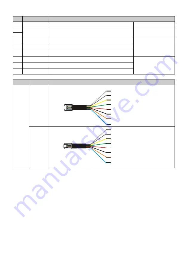
PLUG
RJ45
COM1
RS485
COM2
RS232
PL260
plug-8
8
8 -
7 -
6 -
5 -
4 - COM1-A RS- (MORS. 32)
3 -
2 - COM1-C RS REF (MORS. 33)
1 - COM1-B RS+ (MORS. 31)
1
COM1
RS485
PL260
plug-8
8
8 -
7 -
6 - COM2- RX232
5 - COM2- TX232
4 -
3 - COM2- GND232
2 -
1 -
1
COM2
RS232
Summary of Contents for PL260
Page 1: ...User manual...
Page 2: ...2...
Page 8: ...8 1 4 Size and installation 90 160 mm 43 53 5 45...


