Printer Maintenance • 3
3-9
SV61749 Rev. D
27. Press
Menu
to go back to the previous screen. Use the (
+
) key
to scroll to the next adjustment. The
MODULE DISTANCE to
Sensor
screen displays.
28. Press
Enter
. The
MOD TO SENSOR
screen displays.
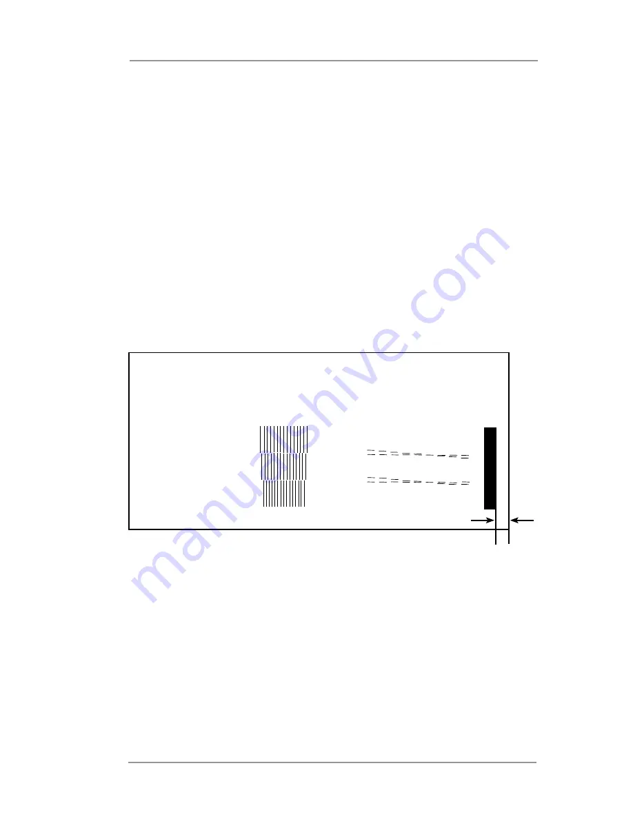
29. On the test pattern that you printed, there is a solid vertical bar at
the far right edge of the pattern. Carefully measure the distance
from the right edge of the bar to the edge of the media that the
test pattern sample printed on.
•
If the gap measures
exactly
.25 in (6.35 mm), then no
adjustment is necessary.
Skip to
step 32.
•
If the gap
is not
exactly
.25 in (6.35 mm),
go to
step 30.
Head 1
Head 2
Head 3
1 2 3 4 5 6 7 8 9
1 2 3 4 5 6 7 8 9
A B C D E F G H I J K L M N O
0.25” Gap
30. You will need to align the print heads to the sensor if the gap
between the solid vertical bar and the right edge of the material
it's printed on does not measure .25 in (6.35 mm). The number
on the
MOD TO SENSOR
screen represents the actual distance
from the sensor to the print head you are aligning. You will need
to increase or decrease that distance. You will use the gap
measurement that you got from the test print to determine how
much to increase or decrease this number by.
Use the 3 samples on the following page to help you determine
the value you should enter.
Sensor Gap Measurement
Summary of Contents for da95f
Page 1: ...Operator Guide International English Version AddressRight DA Series Printer DA95F ...
Page 7: ...Contact Information List vi SV61749 Rev D ...
Page 64: ...3 Printer Maintenance 3 20 SV61749 Rev D ...
Page 74: ...4 Troubleshooting 4 10 SV61749 Rev D ...
Page 82: ...Appendix A Specifications A 8 SV61749 Rev D ...
Page 86: ...A 4 SV61749 Rev D ...


