29
DJM-850-K
5
6
7
8
5
6
7
8
A
B
C
D
E
F
1
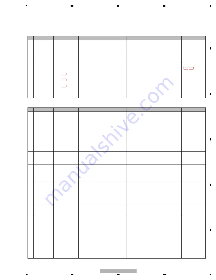
Incorrect setting
PC Setting Utility
1
(at the CD input)
Start up the Setup Utility that has been
installed on the customer’s PC then click
on the MIXER OUTPUT tab.
Check that CH* Timecode CD is selected.
If CH* Timecode PHO
N
O is selected, set it to
CH* Timecode CD.
Operating
instructions
2
Incorrect setting
PC Setting Utility
2
(at the PHO
N
O input)
Start up the Setup Utility that has been
installed on the customer’s PC then click
on the MIXER OUTPUT tab.
Check that CH* Timecode PHO
N
O is
selected.
If CH* Timecode CD is selected, set it to
CH* Timecode PHO
N
O.
Operating
instructions
3
Incorrect setting
DECK mode of
TRAKTOR2
Start up TRAKTOR2 that has been
installed on the customer’s PC then check
that two record icons are displayed next to
the Play button on the track deck.
(If a record icon is displayed, the unit is in
Scratch Control mode, which signifies that
the D
V
S can be used.)
If CUE and CUP are displayed next to the Play
button on the track deck (in Internal Playback
mode), switch to Scratch Control mode. To switch
modes, click on
b
beneath [A], [B], [C] or [D] on
the deck GUI.
TRAKTOR2 manual
4
Incorrect setting
Playback Tracking
mode of TRAKTOR2
Check that one of the two record icons
next to the Play button on the track deck
is lit.
If both their icons are unlit, set TRAKTOR2 to
Playback Tracking mode.
TRAKTOR2 manual
5
Incorrect setting
Timecode signal
input
Select Preferences, Timecode Setup, then
Timecode Inputs on TRAKTOR2, then
check that the double circle is displayed
for the channel to which the timecode
signal is input. (The double circle for
V
I
N
YL is displayed somewhat distorted.
The shapes of the double circles for the
outer and inner tracks are different.)
Perform this check only when a timecode
control CD or
V
I
N
YL (media on which
timecodes are recorded) is available.
If no double circle is displayed, possible reasons
are as follows:
1
The channel for USB AUDIO output of the
DJM-
8
50 and that for USB AUDIO input of
TRAKTOR2 do not match.
→
Check the channel setting on the Input
Routing screen in the Preferences window
of TRAKTOR2 and that of the PC Setup
Utility.
2
Connection between the external device
(DJ player, turntable) and the DJM-
8
50 is not
properly
made.
→
Check the connection and check if the RCA
cables are broken.
—————
[4-2]
N
o timecode signal input to the mixer.
0
Prior
Confirmation
CD/LI
N
E, PHO
N
O,
LI
N
E, USB
*/* selector settings,
PC settings
• Check that the selector is set to USB*/*.
• Check that the driver software dedicated
for the DJM-
8
50 has been installed on
the customer's PC.
• Check that the DJM-
8
50 utility of the
connected PC is set properly.
•
W
hen using a DJ player (when using a
Time code (control CD,)) check that the
DJ player is connected via the CD
connector.
W
hen using a turntable (when
using a Time code (control turntable,))
check that the turntable is connected via
the
PHO
N
O connector.
—————
Operating
instructions
1
Loose connection
/defective parts
MAI
N
Assy
C
N
2602
V
+5
V
BUS
pin 5
D+USB
pin 4
D-USB
pin 3
• Check that the voltage at Pin 5
(
V
+5
V
BUS) of C
N
2602 is about 5
V
(4.75 to 5.25) using a PC connected.
• Check for the D+USB and D-USB
signals.
• If any signal is abnormal, soldering of any part
in the signal path from the PC to the MAI
N
Assy may be defective. Check for any
breakage in the cable and check the soldering
status. If both are OK, replace the defective
part.
• If all signals are normal, soldering of any part
in the signal path from C
N
2602 to the USB
UCOM (IC2603) or the USB UCOM (IC2603)
is defective. Check the soldering status. If
soldering is OK, replace the defective part.
10.35
W
A
V
EFORMS
1-91
1-92
1-93
1-92 1-93
[4] USB
[4-1] Co connection to the PC,
N
o signal is input to and output from the USB connector.
0
Prior
Confirmation
CD/LI
N
E, PHO
N
O,
LI
N
E, USB
*/* selector settings,
PC settings
• Check that the selector is set to USB*/*.
• Check that the driver software dedicated
for the DJM-
8
50 has been installed on
the customer's PC.
• Check that the DJM-
8
50 utility of the
connected PC is set properly.
—————
Operating
instructions
No.
Cause
Diagnostics Point
Item to be Checked
Corrective Action
Reference
No.
Cause
Diagnostics Point
Item to be Checked
Corrective Action
Reference


