AVH-P3100DVD/XN/UC
55
5
6
7
8
5
6
7
8
C
D
F
A
B
E
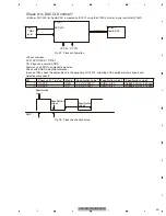
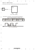
Check 11: Is the video circuit OK?
<Outline> Composite signal and component signal are output from DVD-LSI (IC1501), and are output from the
HOST I/F (CN1901) via a buffer circuit.
CN1901
HOST I/F
Composite
COMPOSITE
Fig 11.1: Video circuit
<Checking method> Playback DVD-REF-A1 TITLE2 CHAPTER5 (WHITE 100%), and monitor COMPOSITE signal with
an oscilloscope with GNDV1 (stylus) being the reference. Set the trigger mode to “TV trigger” and
the trigger line to “150 line”.
IC1501
DVD_LSI
Video
DAC
section
NO.
Check point 1 (stylus)
Specification value
Reference waveform
1
COMPOSITE
1 000 mVpp ± 5 %
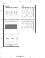
Waveform 6
In case of NG, check the applicable line, the periphery of the major components in the drawing above, soldering of the
peripheral components and defective components.
PEAK
COMPOSITE signal
Reference
value
Color burst
Pedestal level
BOTTOM
Horizontal sync signal
Fig 11.2: Waveform for the case of composite white 100% output
Summary of Contents for AVH-P3150DVD
Page 29: ...AVH P3100DVD XN UC 29 5 6 7 8 5 6 7 8 C D F A B E ...
Page 61: ...AVH P3100DVD XN UC 61 5 6 7 8 5 6 7 8 C D F A B E Side A SCLOCK SDATA D CP_ RESET D DGND2 ...
Page 67: ...AVH P3100DVD XN UC 67 5 6 7 8 5 6 7 8 C D F A B E ...
Page 114: ...AVH P3100DVD XN UC 114 1 2 3 4 1 2 3 4 C D F A B E 9 1 PACKING ...
Page 116: ...AVH P3100DVD XN UC 116 1 2 3 4 1 2 3 4 C D F A B E 9 2 EXTERIOR 1 A A A B ...
Page 118: ...AVH P3100DVD XN UC 118 1 2 3 4 1 2 3 4 C D F A B E 9 3 EXTERIOR 2 A A E F 2 1 ...
Page 123: ...AVH P3100DVD XN UC 123 5 6 7 8 5 6 7 8 C D F A B E ...
Page 127: ...AVH P3100DVD XN UC 127 5 6 7 8 5 6 7 8 C D F A B E ...
Page 145: ...AVH P3100DVD XN UC 145 5 6 7 8 5 6 7 8 C D F A B E ...

