background image

Installation and Wiring

5-4

Operating Manual: PMImicro diag

Connecting the device

When connecting the PMImicro diag to the PC and to a device that

supports expanded PVIS diagnostics, please refer to the connection dia-

gram and the corresponding cable connection details (see page 4-6 ff).
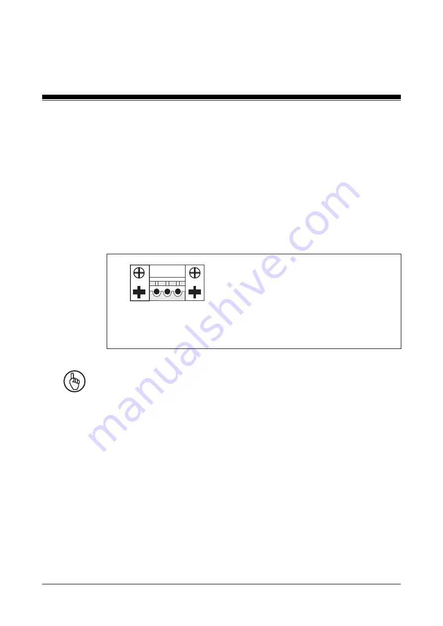
Supply voltage

The 24 VDC supply voltage connection is on the side of the housing (see

Fig. 4-2).

Fig. 5-3: Layout of supply voltage connector

1   2   3

1: Earthing
2: 0 V
3: + 24 VDC

Notice

Please note the following during diagnostics on the PNOZmulti.

The RS 232 interfaces on the PNOZmulti and PMImicro diag do not have

galvanic isolation. If the units are connected to different voltage sources,

any potential difference between the power supplies could destroy the RS

232 interface.

Connect the PNOZmulti and PMImicro diag to the same voltage source!

Cable layout

• Electrical or electronic components which could cause interference

(contactors, thyristors, relay coils and solenoid valve coils) should be

physically separate from data lines.

We recommend you use a sheet metal (MU metal) bulkhead between

both areas.

Summary of Contents for PMI m107 diag

Page 1: ...PMI P GLDJ Operating manual 21167 EN 06 Operator terminals ...

Page 2: ... Copies may be made for internal purposes Suggestions and comments for improving this documentation will be gratefully received Pilz PIT PMI PNOZ Primo PSEN PSS PVIS SafetyBUS p SafetyEYE SafetyNET p the spirit of safety are registered and protected trademarks of Pilz GmbH Co KG in some countries SD means Secure Digital ...

Page 3: ...delines 3 1 Use of qualified personnel 3 2 EMCD 3 2 Warranty and liability 3 2 Disposal 3 2 Unit Description 4 1 Front view 4 1 Key functions 4 1 Side view including interfaces 4 2 Side view including CF card slot 4 3 Inserting the CF card 4 3 Interfaces 4 4 Termination 4 5 Connection diagram and details of cables and converters PSS SafetyBUS p 4 6 Connection diagram and details of cables and conv...

Page 4: ...SafetyBUS p and PNOZmulti 6 1 PNOZmulti vIO 6 1 Procedure after power up 6 1 Default setting 6 2 Help 6 4 PMImicro configuration 6 4 Configuration 6 5 General guidelines on operation 6 7 Display when window is opened 6 7 Display when input field is activated 6 7 Direction of selection in the options list 6 7 Password protection 6 8 User setting 6 9 Select user 6 10 Change user name 6 11 Change pas...

Page 5: ... 26 Project name 6 27 Integrity display PNOZmulti 6 27 Status 6 27 CRC 6 28 Project name 6 28 Show delete information 6 29 Display mode 6 29 Max number of entries in the event list 6 30 Language 6 32 Menu language 6 32 Diagnostic language 6 32 Display settings 6 33 Log files 6 35 PMImicro diag log file 6 35 Diagnostic log file 6 37 Versions 6 39 Operation 7 1 Download data 7 1 Diagnostic configura...

Page 6: ...on between event messages 7 10 Deleting event message 7 11 Deleting event message on display 7 11 Incoming event message 7 12 Managing event messages 7 12 PNOZmulti diagnostics via virtual outputs 7 13 Schematic representation using the virtual output VO1 as an example 7 14 Create diagnostics 7 16 Configuration files 7 16 mappingtable xml 7 18 Message files 7 19 Message display 7 22 Part counter 7...

Page 7: ...ises The hardware description for the PMImicro diag A description of the PMImicro configuration A description of the diagnostics Sourcecodefromthird partymanufacturersoropensourcesoftwarehasbeenusedfor some components of the PMI micro diag You will find the respective licences in the document Licensing information No 1003220 INFORMATION Details of how to create the diagnostic configuration and how...

Page 8: ... information on safety regulations and intended use 4 Unit Description This chapter describes the individual components of the diagnostic terminal 5 Installation and Wiring This chapter explains how to install and wire up the diagnostic terminal 6 Commissioning This chapter describes the commissioning the default settings and the PMImicro configuration 7 Operation This chapter describes the data t...

Page 9: ...ituation which could lead to serious injury or death and indicates preventive measures that can be taken CAUTION This refers to a hazard that can lead to a less serious or minor injury plus material damage and also provides information on preventive measures that can be taken NOTICE This describes a situation in which the unit s could be damaged and also provides information on preventive measures...

Page 10: ...Introduction 1 4 Operating Manual PMImicro diag Notes ...

Page 11: ...ted on the PC in the relevant system software for the connected device it is then downloaded to the PMImicro diag via a serial interface or CF card using the PMImicro Configurator Other settings such as password settings language interfaces and user settings are required for the diagnostic terminal itself The PMImicro configuration can be made directly on the diagnostic terminal via the navigation...

Page 12: ...elected PMImicro configuration The PMImicro configuration created in the PMImicro Configurator in the system software of the connected device determines which language is selected Log files If the relevant configuration supports multiple languages the language may later be switched for viewing and exporting the log files Components Display LCD 2 8 70 mm 128 x 64 pixels Interfaces Two serial interf...

Page 13: ...fy the error The PMImicro Configurator is required in order to download the diagnostic configuration The following is deemed improper use Any component technical or electrical modification to the diagnostic terminal Use of the diagnostic terminal outside the areas described in this manual Use of the diagnostic terminal outside the stated technical details see chapter entitled Technical Details Int...

Page 14: ...ty technology EMCD The diagnostic terminal is designed for use in an industrial environment It is not suitable for use in a domestic environment as this can lead to interference Warranty and liability All claims to warranty and liability will be rendered invalid if The diagnostic terminal was used contrary to the purpose for which it is intended Damage can be attributed to not having followed the ...

Page 15: ...ose help for the current window Call up main setup menu by holding the key down for 3 sec Close current window cancel an entry In diagnostic mode the event or action will appear see page 7 6 ff Switch to page two in the log files menu Confirm entry or selection of menu options Move in the direction of the arrows scroll function up down Change selection of characters 1 9 _ A Z Switch to the next me...

Page 16: ...5 RS 485 interface termination Notice Please note the following during diagnostics on the PNOZmulti The RS 232 interfaces on the PNOZmulti and PMImicro diag do not have galvanic isolation If the units are connected to different voltage sources any potential difference between the power supplies could destroy the RS 232 interface Connect the PNOZmulti and PMImicro diag to the same voltage source IN...

Page 17: ...ta on the CF card will be lost or the CF card itself may be damaged if you insert or exchange the CF card while the PMImicro diag is switched on Inserting the CF card INFORMATION Please refer to the guidelines given by the manufacturer of the CF card All CF cards use Type I will only fit into the PMImicro diag in one direction and the right way round Please note the following Do not twist the CF c...

Page 18: ...sert the CF card you may need to adjust the position of the CF card within the slot Do not force the CF card into the card slot This will damage the CF card or the PMImicro diag Interfaces Layout of the RS 232 interface 6 7 8 9 1 2 3 4 5 RxD TxD DTR GND DSR RTS CTS n c DCD 6 7 8 9 1 2 3 4 5 A B n c n c n c GND n c n c n c Layout of the RS 485 interface 9 pin D Sub connector View from contact side ...

Page 19: ...ing Manual PMImicro diag Termination The RS 485 interface can be terminated internally R 120 Ohm Switch 4 1 off Termination on Termination off RS485 OFF ON 1 3 2 4 RS485 OFF ON 1 3 2 4 Switch 4 on Switch 3 1 off ...

Page 20: ...ails of cables and converters PSS SafetyBUS p PSS SafetyBUS p converter Fig 4 6 Connection diagram and details of cables and converters PSS SafetyBUS p Description RS 232 download cable RS 485 download cable RS 232 0 modem cable RS 232 0 modem cable PC PSS RS 232 RS 485 interface converter Order number 301960 374205 301965 310300 305159 No 1 2 3 4 5 CF card or PC or ...

Page 21: ...les and converters PNOZmulti PMImicro diag RS 232 RS 485 RS 232 RS 232 RS 485 RS 232 RS 485 2 2 RS 232 RS 232 RS 485 5 3 4 3 4 5 PNOZmulti PC or converter converter or or Description RS 485 download cable RS 232 0 modem cable RS 232 0 modem cable PC PSS RS 232 RS 485 interface converter Order number 374205 301965 310300 305159 No 2 3 4 5 CF card ...

Page 22: ...tion The PMImicro diag has 2 interfaces 1 x RS 232 and 1 x RS 485 These can be used for communication with either the connected device or the PC INFORMATION The interface may be configured either on the PMImicro diag or in the PMImicro Configurator ...

Page 23: ...p as large a distance as possible between the system and any electromagnetic fields particularly when frequency converters are nearby To avoid the build up of heat a distance of 10 cm 3 94 should be maintained all round the unit Protect the unit from direct sunlight and dust Do not use chemicals close to the unit Ensure the maximum permissible ambient and operating temperatures are not exceeded En...

Page 24: ...tion and Wiring 5 2 Operating Manual PMImicro diag Mounting cut out Fig 5 1 Nominal dimensions PMImicro diag Nominal dimensions 148 5 826 78 3 071 51 2 008 66 2 598 7 3 0 28 135 8 5 354 138 1 5 433 68 0 7 2 677 ...

Page 25: ...bient and operating temperatures in the technical details is observed IP65 protection can only be guaranteed when the fixing screws are sufficiently tightened the gasket is not damaged the wall thickness is at least 2 5 mm NOTICE For installation attach the retaining clamps to the left and right of the device see figure Other types of attachment can lead to strain on the housing front The torque s...

Page 26: ... 2 0 V 3 24 VDC Notice Please note the following during diagnostics on the PNOZmulti The RS 232 interfaces on the PNOZmulti and PMImicro diag do not have galvanic isolation If the units are connected to different voltage sources any potential difference between the power supplies could destroy the RS 232 interface Connect the PNOZmulti and PMImicro diag to the same voltage source Cable layout Elec...

Page 27: ...air cables Earth connector Connect the earthing socket on the housing M4 press fit socket on the side of the housing to the earth bus bar on the control cabinet or unit Use as short a copper conductor as possible cross section min 2 5 mm 2 If there are several units in the control cabinet or plant ensure the earth conductor is connected in a star formation on the bus bar The earth conductor cross ...

Page 28: ... connected to a bus bar The connection between the bus bar and the control cabinet system should be as short as possible and with low impedance Fasten the braided screening to the screen bar over as large a surface area as possible e g with metal hose clips or polyurethane PU cable clips Measures to protect against interference voltages Wire inductive loads e g contactor coils relay coils and sole...

Page 29: ...ag 1 Earth star point on unit or control cabinet 2 Earth bus bar 3 Supply voltage 4 Earthing terminal electronic 5 Earthing bolt housing 6 Data line screening Fig 5 5 Connection example 1 24 VDC 2 0 V 3 4 5 3 4 5 6 Connection example ...

Page 30: ...Installation and Wiring 5 8 Operating Manual PMImicro diag Notes ...

Page 31: ... on the system software of the connected device PNOZmulti vIO With the PNOZmulti activate the serial interface in the module configuration Use the sample project to create a diagnostic configuration and download this to the PMImicro diag see page 7 13 ff Procedure after power up There may be a time delay of a few seconds between power up and the unit being ready for operation depending on the size...

Page 32: ...tting English Interfaces Factory default setting COM1 RS 232 Connected device COM2 RS 485 PC Connected device PNOZmulti Device diagnostic configuration The device diagnostic configuration supports the following default projects on the PMImicro diag factory default setting PSS Safety BUS p PSS Safety BUS p Diagnostics for all system errors in two languages German English PNOZmulti Diagnostics for a...

Page 33: ...as you wish INFORMATION If you switch between projects the settings that you made in the setup will be lost As it starts up the PMImicro diag uses the selected configuration to decide which diagnostics to start INFORMATION If a new diagnostic configuration standard PSS project standard PNOZmulti or standard PNOZmulti vIO project is downloaded to the PMImicro diag using the PMImicro Configurator or...

Page 34: ... see page 7 25 ff INFORMATION Please refer to the table showing the key functions see page 4 1 Hold the ESC key down for three seconds This will access the main menu The following settings may be made Configuration Setting for password protection interfaces etc Language Setting for menu language and diagnostic language INFORMATION The language selected for the diagnostic language depends on the di...

Page 35: ...PMImicro Config Deleting and exporting the log files Log files User setting Three access levels may be configured for the PMImicro diag These may be assigned different access rights Interfaces Select the connected device and configure the PMImicro diag interface for connection to the connected device e g PSS for connection to the PC Time characteristic Set the operator timeout and flash frequency ...

Page 36: ...ity device and Equip ID are shown on page 1 and the description location description and text of event message or action on page 2 Description details The description is shown on page 1 and the details on page 2 Description only Only the page with the description is shown Please note This display mode is not recommended because it does not show the details so important location information about t...

Page 37: ...ctive input field is selected when it is bordered by a dotted line 1 Press ENTER This will access Display when input field is activated The relevant setting is activated when the background on the input field is black 2 Fig 6 1 Display when window is opened 1 Fig 6 2 Display when input field is activated 2 ...

Page 38: ...assword protection Two areas may be password protected Changing the configuration of the PMImicro diag Config Deleting and exporting log files Proceed as follows 1 Hold the ESC key down for three seconds This will access the main menu 2 Using the navigation keys select Configuration 3 Press ENTER 4 Using the navigation keys select Password protection 5 Press ENTER 6 Two areas are available for sel...

Page 39: ...and the selection window turns black 13 Using the navigation keys select ON OFF 14 Press ENTER Your selection is saved 15 Press ESC to exit the menu User setting Three access levels may be configured for the PMImicro diag These may be assigned different access rights The default user and settings are User CONFIG LOGFILE ADMIN Password 100000 200000 300000 Access right 0 1 0 and 1 Display The areas...

Page 40: ...seconds This will access the main menu 2 Using the navigation keys select Configuration 3 Press ENTER 4 Using the navigation keys select User setting 5 Press ENTER 6 Three users are available for selection 7 Using the navigation keys select the user whose settings you wish to change e g 03 ADMIN Fig 6 4 User setting ...

Page 41: ...ter Select the character using the navigation keys Select the new character using the navigation keys Delete character Using the navigation keys place the cursor next to the character that is to be deleted Press Insert character Using the navigation keys place the cursor next to a character and press The following characters can be selected A Z _ 0 9 3 Press ENTER Your selection is saved 1 Fig 6 5...

Page 42: ...R The password 2 becomes visible and can be changed The cursor flashes at the spot at which a character can be replaced Proceed as follows Replace character Select the character using the navigation keys Select the new character using the navigation keys The password has six characters The following characters can be selected A Z 0 9 4 Press ENTER Your selection is saved 5 Press ESC to exit passwo...

Page 43: ...he access right can be changed Two access rights can be assigned 0 PMImicro configuration 1 Delete and export log files Example Select the area using the navigation keys The field turns black Using the navigation keys select or de select the access right for the area 4 Press ENTER Your selection is saved Access right 0 selected Access right 1 de selected Access right 0 de selected Access right 1 s...

Page 44: ...select COM1 as the interface for the connected device COM2 will automatically be set as the interface for the PC and vice versa Interface for the connected device Proceed as follows 1 Hold the ESC key down for three seconds This will access the main menu 2 Using the navigation keys select Configuration 3 Press ENTER 4 Using the navigation keys select Interfaces 5 Press ENTER 6 The selection window...

Page 45: ...ion it will no longer be possible to choose between the connected devices Proceed as follows 1 Hold the ESC key down for three seconds This will access the main menu 2 Using the navigation keys select Configuration 3 Press ENTER 4 Using the navigation keys select Interfaces 5 Press ENTER 6 Using the navigation keys select the window for the connected device 7 Press ENTER and the selection window t...

Page 46: ...onfiguration 3 Press ENTER 4 Using the navigation keys select Interfaces 5 Press ENTER 6 Using the navigation keys select PC interface 7 Press ENTER and the selection window turns black 8 Using the navigation keys select the required interface for PC communication 9 Press ENTER Your selection is saved A prompt appears asking if you wish to restart the PMImicro diag 10 Using the navigation keys sel...

Page 47: ...ll need to log in again if the Operator timeout has elapsed Proceed as follows 1 Hold the ESC key down for three seconds This will access the main menu 2 Using the navigation keys select Configuration 3 Press ENTER 4 Using the navigation keys select Time characteristics 5 Press ENTER 6 The selection window for Operator timeout is pre selected 7 Press ENTER and the selection window turns black 8 Us...

Page 48: ...ress ENTER 4 Using the navigation keys select Time characteristics 5 Press ENTER 6 Using the navigation keys select the window for Flash frequency 7 Press ENTER and the selection window turns black 8 Using the navigation keys set the required value The following values are available for selection High Normal Low A symbol is displayed showing the corresponding flash frequency 9 Press ENTER Your sel...

Page 49: ... ENTER 6 The selection window for Date is pre selected 7 Press ENTER the numeric value that can be changed is flashed and shaded black 8 Using the navigation keys set the required date Date format YYYY MM DD 9 Press ENTER Your selection is saved 10 Using the navigation keys select the window for Time 11 Press ENTER the numeric value that can be changed is flashed and shaded black 12 Using the navi...

Page 50: ... diag before inserting or exchanging the CF card Data on the CF card will be lost or the CF card itself may be damaged if you insert or exchange the CF card while the PMImicro diag is switched on Proceed as follows 1 Hold the ESC key down for three seconds This will access the main menu 2 Using the navigation keys select Configuration 3 Press ENTER 4 Using the navigation keys select Backup Restore...

Page 51: ... for Identifier 11 Press ENTER and the selection window turns black 12 Using the navigation keys set the required identifier The identifier labels the selected data This way several backups can be stored and managed on one CF card The following identifiers are available for selection 01 10 13 Press ENTER 14 Using the navigation keys select the data you wish to copy 15 Press ENTER the option is sel...

Page 52: ...ed identifier such as the PMImicro configuration runtime and diagnostic configuration is deleted before the information is copied to the CF card 17 Press ENTER the option is selected 18 Using the navigation keys select Start 19 Press ENTER 20 A window appears with a prompt asking if you wish to send the data 21 Using the navigation keys select Yes No and then confirm your selection by pressing ENT...

Page 53: ...for three seconds This will access the main menu 2 Using the navigation keys select Configuration 3 Press ENTER 4 Using the navigation keys select Backup Restore 5 Press ENTER 6 The selection window for backup or restore is pre selected 7 Press ENTER and the selection window turns black 8 Using the navigation keys select the window for the direction CF card Data can then be written from the CF car...

Page 54: ...t the required identifier Only the identifiers for the files that are on the CF card are available 13 Press ENTER 14 Using the navigation keys select the data you wish to copy Only the data that is on the CF card is available to select 15 Press ENTER the option is selected Fig 6 11 Restore select data Fig 6 12 Restore start download ...

Page 55: ...TER 18 A window appears with a prompt asking if you wish to send the data 19 Using the navigation keys select Yes No and then confirm your selection by pressing ENTER YES The data is downloaded No The data is not downloaded 20 Press ENTER to confirm the message 21 Press ESC to exit the menu ...

Page 56: ... the PSS ST user program for the standard section of the PSS PSS diagnostic configuration in the PSS PMI diagnostic configuration in the PMImicro diag The following status conditions may be displayed Status OK Invalid project Obsolete No information Key The component is in order The component belongs to another project The component is obsolete No information is available on the current configurat...

Page 57: ...e diagnostic configuration on the PMImicro diag must be compatible with the program containing the diagnostic configuration on the connected device in order for diagnostics to be performed correctly The display is divided into Status Indicates the status for the following components PNOZ program and diagnostic configuration in the PNOZmulti PMI diagnostic configuration in the PMImicro diag The fol...

Page 58: ...ing components PNOZ program and diagnostic configuration in the PNOZmulti PMI diagnostic configuration in the PMImicro diag Project name Displays the name of the following components PNOZ program and diagnostic configuration in the PNOZmulti PMI diagnostic configuration in the PMImicro diag ...

Page 59: ...5 Press ENTER 6 Press ENTER to select or deselect the Show Info option Fig 6 13 Show delete information Display mode Set the display mode Proceed as follows 1 Hold the ESC key down for three seconds This will access the main menu 2 Using the navigation keys select Configuration 3 Press ENTER 4 Using the navigation keys select Display mode 5 Press ENTER 6 The selection window for display mode is pr...

Page 60: ...estart the PMImicro diag later in order to activate the interface selection Max number of entries in the event list Set the max number of entries in the event list Proceed as follows 1 Hold the ESC key down for three seconds This will access the main menu 2 Using the navigation keys select Configuration 3 Press ENTER 4 Using the navigation keys select Event list 5 Press ENTER 6 Press ENTER again t...

Page 61: ...the navigation keys select YES 10 Press ENTER 11 The PMImicro diag is restarted INFORMATION In Step 9 if you select NO with the navigation keys the unit will not be restarted In this case the length of the event list will automatically be reset to the previous value If digit 1 has the value 1 digits 2 and 3 cannot be set to values greater than 0 If digits 2 or 3 are greater than 0 digit 1 cannot b...

Page 62: ...Language 3 Press ENTER 4 The selection window for Menu language is pre selected 5 Press ENTER and the selection window turns black 6 Using the navigation keys select the required language 7 Press ENTER Your selection is saved 8 Press ESC to exit the menu Diagnostic language The diagnostic language is the language in which the event messages and actions are displayed INFORMATION The language select...

Page 63: ...indicates the value will flash 6 Using the navigation keys select the required value 7 Press ENTER The selection is saved 8 Using the navigation keys select the window for Lighting 9 Press ENTER and the selection window turns black The following options can be selected Off Backlighting is always off Dimmed Backlighting is always dimmed On Backlighting is always on Dimmed Off Backlighting switches ...

Page 64: ...Operating Manual PMImicro diag 6 34 Commissioning 10 Press ENTER Your selection is saved 11 Press ESC to exit the menu ...

Page 65: ...ser setting see page 6 8 for password protection see page 6 7 PMImicro diag log file This is where the start behaviour for the PMImicro diag is recorded along with any errors that occur in the process Proceed as follows 1 Hold the ESC key down for three seconds This will access the main menu 2 Using the navigation keys select Log files 3 Press ENTER 4 The selection window for Log files is pre sele...

Page 66: ... window appears with a prompt asking if you wish to delete the files 16 Using the navigation keys select Yes No and then confirm your selection by pressing ENTER YES The files are deleted No The files are not deleted 17 Press ESC to exit the menu Export The entries are saved on to a CF card in the menu language that is currently selected see page 6 19 NOTICE Switch off the PMImicro diag before ins...

Page 67: ... of which event message has been added deleted and when INFORMATION The diagnostic log file contains the event messages plus a description of the event INFORMATION When performing diagnostics on the PNOZmulti a location description is also displayed The location description is created by the user himself and is entered in the PNOZmulti Configurator Proceed as follows 1 Hold the ESC key down for th...

Page 68: ...the display Delete 14 Press ENTER 15 A window appears with a prompt asking if you wish to delete the files 16 Using the navigation keys select Yes No and then confirm your selection by pressing ENTER YES The files are deleted No The files are not deleted 17 Press ESC to exit the menu Export The event messages are saved on to a CF card in the diagnostic language that is currently selected see page ...

Page 69: ... the action 26 Using the navigation keys select Yes No and then confirm your selection by pressing ENTER YES The event messages are exported No The event messages are not exported 27 Press ENTER to confirm the message 28 Press ESC to exit the menu Versions This is where you will find information on runtime hardware operating system etc for service purposes ...

Page 70: ...Operating Manual PMImicro diag 6 40 Commissioning Notes ...

Page 71: ... to perform diagnostics The diagnostic configuration is created on the PC in the relevant system software for the connected device it is then downloaded to the PMImicro diag via a serial interface or CF card using the PMImicro Configurator PMImicro configuration The PMImicro configuration comprises settings such as password settings language interfaces and user settings which are required for the ...

Page 72: ...diagnostics are recorded i e details of which event message has been added deleted and when The log can be exported to a CF card Runtime This is the software that enables the PMImicro diag to run The runtime can be saved on to a CF card and restored if necessary Please refer to Chapter 6 for details of the backup restore function see page 6 19 ff Communication relating to runtime Connected device ...

Page 73: ...the PMImicro diag recognises that the data has to be passed on It exits diagnostic mode and switches to routing mode If routing mode is inactive for an extended period the PMImicro diag switches back to diagnostic mode due to the timeout INFORMATION For the routing function the maximum timeout period for the PG interface must be set in PSS WIN PRO The PNOZmulti requires a configurator that support...

Page 74: ...ust be connected to the RS 232 interface The diagnostic function on the programmable safety system must be activated The diagnostic configuration on the PMImicro diag must match the diagnostic configuration on the programmable safety system The PMImicro diag is supplied with a default diagnostic configuration and a default PMImicro configuration so it can immediately be used for device diagnostics...

Page 75: ...em software from Version 5 0 0 it is possible to create the diagnostic configuration in a given language e g German English If this diagnostic configuration is downloaded to the PMImicro diag the available languages are replaced PMImicro Configurator The PMImicro Configurator is part of the PSS WIN PRO and PNOZmulti Configurator system software and performs the following tasks The PMImicro Configu...

Page 76: ...arn the user about a potential or imminent critical machine status Status information This priority class contains event messages which describe the current status of the process and or machine These event messages are provided for information the production cycle is not impeded nor is it adversely affected Responsibilities An area of responsibility can be assigned to each action The responsibilit...

Page 77: ...e to examine whether the event message corresponding to the event has to be displayed and entered in the event list intelligent evaluation For example if it concerns an event that has occurred as a consequence of a previous event the event will be ignored A check is also made to see whether the user requires further information on an event For example if the PSS registers that an I O Group on Safe...

Page 78: ... class type size 6 x 8 pixels 2 7 x 4 7 mm 4 Symbols for priority classes only displayed when an entry is present flashes until the entry is displayed 5 Date YYYY MM DD Time hh mm ss 6 Scope 7 Device 8 Equip ID equipment identifier and parameter 9 Responsibility 10 Description of location 11 Description of event or action Fig 7 1 Message display press 2 4 3 1 5 8 7 6 press press 9 Description of e...

Page 79: ...escribed see page 4 1 you can access the display for the error message and the remedy action Fig 7 2 Navigation within an event message ENTER Error Page 1 X Action 1 Page 1 1 Action 8 Page 1 8 Error Page 2 Action 1 Page 2 Action 8 Page 2 ENTER ENTER ENTER ESC Timeout 15 sec ENTER ENTER ESC Timeout 15 sec ENTER ESC Timeout 15 sec ENTER ESC Timeout 15 sec ...

Page 80: ...pective event message and the corresponding remedy action Fig 7 3 Navigation between event messages Event message 1 Page X Event message 2 Page X Event message 3 Page X Event message 2 Page 1 1 Event message 2 Page 2 2 INFORMATION The length of time a selected message is displayed depends on the set operator timeout Once the operator timeout has elapsed the display will return to the highest prior...

Page 81: ...message The following diagram shows the event messages that are displayed when an event message is deleted from the PSS Subsequent event messages move up automatically the event messages are shifted Deleting event message on display If the event message 3 5 that is currently displayed is deleted by the PSS a window will appear showing the message Message deleted The event message will remain visib...

Page 82: ...o its priority Existing event messages in the event list are shifted accordingly The corresponding priority class symbol will flash the event message that is currently displayed will remain there Managing event messages The event messages are recorded in the diagnostic log file i e details of which event message has been added deleted and when ...

Page 83: ...as plain text messages When a virtual output in the PNOZmulti is set the stored message is displayed when the output is reset the message is hidden The signals are processed independently from each other Users create the message texts on the PC in the languages they require then save them in a message file in XML format It is possible to switch languages on the PMImicro The message file is downloa...

Page 84: ... output VO01 as an example PNOZmulti Language switching example English PMImicro diag Display mappingtable xml Message file de xml Message file en xml Signal VO1 text17 0 3 2 1 23 text17 text00 English Deutsch lang text text17 Ausgang 01 text17 Output 01 text00 Beispiel Example text00 lang text 01 Output 01 Virtual output VO 0 23 1 2 3 4 5 6 Virtual input VO 0 23 ...

Page 85: ...mappingtable xml The transmitted VO1 signal is assigned an identification label This means that the assignment of virtual outputs to message texts can be flexible 4 Language switching It is possible to define the message file that will be searched for the identification label 5 Message file In the message file the identification label determines which message text is displayed see User message pag...

Page 86: ...message texts in the required languages and add these to the corresponding message file see page 7 20 4 In the message file assign an identification label to each of the message texts see page 7 18 5 Save this message file as an XML file in the languages folder see Fig 7 6 6 Copy the backup folder into the main directory of a CF card 7 Download this configuration to the PMImicro diag using the res...

Page 87: ...directory structure must be maintained if the files are to be downloaded to the PMImicro diag using the restore function CD backup de xml en xml id_01 config pmimicro prj1 languages mappingtable xml xx xml Fig 7 6 Configuration files directory structure ...

Page 88: ...ssign it to a different message in the message files key name 2 text_017 key The identification label text_017 is assigned to virtual output 2 This identification label is then assigned to the corresponding message in the message files xml version 1 0 encoding UTF 8 configuration comment Demo from 2005 10 17 comment Identification label Virtual output 0 23 section name vo mapping key name 0 text_0...

Page 89: ...for the message file may contain a maximum of 2 characters and must be in lower case As the PMImicro diag is started up the directory for the message files is read in and all available languages are included in the language selection The languagetext entry in the message file is used for displaying the available languages in the language selection see Fig 7 8 key name languagetext Deutsch key If a...

Page 90: ...F 8 configuration comment Demo from 2005 10 17 comment key name languagetext Deutsch key Freely available e g project name date author etc section name texts key name text_no_connection Keine Verbindung key key name text_no_run PNOZmulti ist in STOPP key key name text_000 Sample_text 0 key key name text_001 Sample_text 1 key key name text_002 Sample_text 2 key Text for diagnostic language selectio...

Page 91: ... text is assigned to the corresponding identification label in the mappingtable xml file Special messages Special messages are messages relating to operational readiness and the connection to the connected device These messages are generated by the PMImicro diag The message texts themselves can be amended by the user but their assignment is fixed The following events are displayed as special messa...

Page 92: ... requires more than 6 lines Use the navigation keys to scroll The messages are sorted in accordance with the signals from the virtual output VO0 VO23 The message for VO0 if set is always shown first followed by the message from VO1 etc All messages are marked by a square bullet point INFORMATION If a message text cannot be found within the message file the corresponding identification label will i...

Page 93: ...he PNOZmulti If the part counter is switched off a message text is assigned to virtual output VO23 If the counter value is 00000 virtual input VI23 on the PNOZmulti is set This acts as feedback to the PNOZmulti This feedback can be processed further in the PNOZmulti INFORMATION The settings for counter direction and counter status are retained even after the PMImicro diag is restarted Fig 7 10 Par...

Page 94: ...ard counter starts as soon as a counter pulse is received Part counter backwards Proceed as follows 1 Press either of the two navigation keys This will access the counter s setup menu 2 Using the navigation keys select backward 3 Press ENTER The option is selected 4 Using the navigation keys select the counter value xxxxx 5 Press ENTER The numeric value that can be set is flashed and shaded black ...

Page 95: ...ORMATION If the part counter is switched off a message text is assigned to virtual output VO23 PMImicro configuration INFORMATION This section contains specific guidelines for configuring diagnostics on the PNOZmulti vIO For information on other settings relating to the PMImicro configuration please refer to Chapter 6 from page 6 4 ff Password protection Logbook setting has no effect as no logbook...

Page 96: ...Operation 7 26 Operating Manual PMImicro diag Logbook The logbook function is not supported on PNOZmulti vIO diagnostics and is greyed out in the menu Versions Display on the PNOZmulti CRC and date ...

Page 97: ...60068 2 14 11 99 Storage temperature EN 60068 2 1 2 07 94 Climatic suitability EN 60068 2 78 10 01 Condensation Vibration EN 60068 2 6 04 95 Shock EN 60068 2 27 03 93 12 32 VDC 24 VDC LC dot matrix graphic module 128 x 64 Bit 60 x 40 mm W x H White LEDs 1 x RS 232 1 x RS 485 RS 232 10 m RS 485 1000 m max 110 kBit s 50 pin RISC processor mClinux 8 MByte Flash 32 MByte SDRAM Battery buffered real ti...

Page 98: ...l PMImicro diag 8 2 Technical Details Mechanical data Housing material Housing Front Dimensions with front panel H x W x D Modular depth Weight Stainless steel ABS Polyflam UL listed 78 mm x 148 mm x 57 mm 51 mm 370 g ...

Page 99: ...uraNET p Pilz PIT PMCprotego PMI PNOZ Primo PSEN PSS PVIS SafetyBUS p SafetyEYE SafetyNET p the spirit of safety are registered and protected trademarks of Pilz GmbH Co KG in some countries We would point out that product features may vary from the details stated in this document depending on the status at the time of publication and the scope of the equipment We accept no responsibility for the v...

Reviews: