IMS-4840 External Power Sensor
Installation Instructions
Introduction
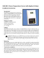
The IMS-4840 External Power Sensor lets you monitor
power anywhere within your infrastructure. It reports any
loss of power and measures the current voltage in the
circuit, allowing you to know the status of each server
rack and even of your remote UPS. Any failed generator
starts are reported to you immediately. The IMS-4840 can
monitor voltage from 0–250VAC 50/60Hz.
Package Contents
(1) IMS-4840 Power Sensor
(2) Plastic drywall anchors
(2) #6 Metal tapping screws
(4) Rubber feet
Cabling
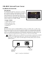
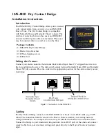
The Power Sensor connects to the IMS-4000 Host or Node via an RJ-45 cable (e.g. CAT5 cable).
The connection from the sensor to the Host or Node can utilize your existing network wiring infra-
structure. For example, the sensor may be installed in another room or another floor. Connect the
sensor to your structured wiring network via an RJ-45 jack. At the other end, connect a patch cable
from your structured wiring patch panel directly to the Host or Node environment input.
!
Caution:
The IMS sensors are not TCP/IP devices and therefore should not be connected
directly to any wiring infrastructure that is connected to network equipment such as a
hub, router, or switch. Sensors use RJ-45 plugs and cables similar to those used with
Ethernet devices.
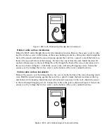
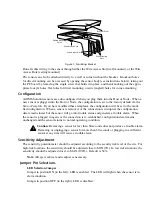
Figure 1: Connections to the IMS-4840
IMS-4000 Manual
128
Summary of Contents for Sensaphone IMS-4000
Page 1: ...IMS 4000 User s Manual Version 2 4 8 PHONETICS INC SENSAPHONE ...
Page 44: ......
Page 59: ......
Page 60: ......
Page 102: ......
Page 106: ...IMS 4000 Manual 106 ...
Page 135: ...Chapter 7 IMS 4000 Sensors 135 ...
Page 146: ...IMS 4000 Manual 146 ...
Page 148: ...IMS 4000 Manual 148 ...
Page 158: ...IMS 4000 Manual 158 ...
Page 159: ...159 ...


