Bus Configuration for I/O Modules (RAD-ISM-900-EN-BD-BUS only)
2476_en_I
PHOENIX CONTACT
5-27
5.6.7
Digital Pulse Output Module
The Digital Pulse Output Module accurately reproduces pulse counts or frequency outputs
from data contained in PLC registers. It is compatible with mechanical relays and electronic
pulse input devices. Upon power loss, the pulse output is set to 0 Hz.
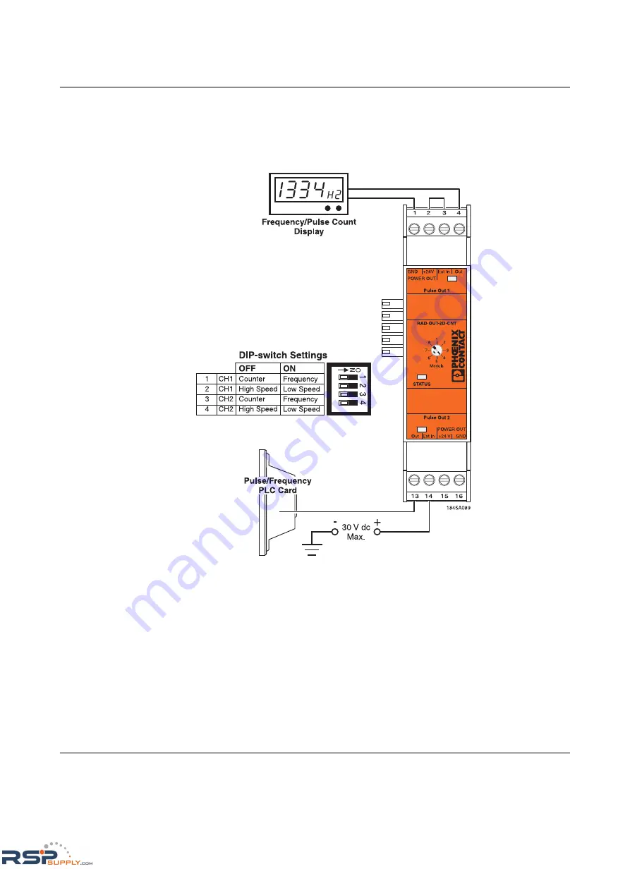
Figure 5-12
RAD-OUT-2D-CNT Digital Pulse Output Module wire diagram
DIP Switch Settings
The DIP switch settings listed below are applicable for both channel 1 and channel 2. Refer
to Figure 5-12 for DIP switch configurations.
Counter/Frequency Mode
When counter mode is selected, the module will output a specific number of pulses as
determined by the PLC value written to it. If frequency mode is selected, the pulse output
module will generate pulses with a 50% duty cycle. In frequency mode, the low or high
speed switch setting is ignored.
RSPSupply - 1-888-532-2706 - www.RSPSupply.com
http://www.RSPSupply.com/p-12970-Phoenix-Contact-2900016-Radio-900-MHz-Ethernet-Radio.aspx


