Installation
2476_en_I
PHOENIX CONTACT
3-3
3
Installation
3.1
Mounting
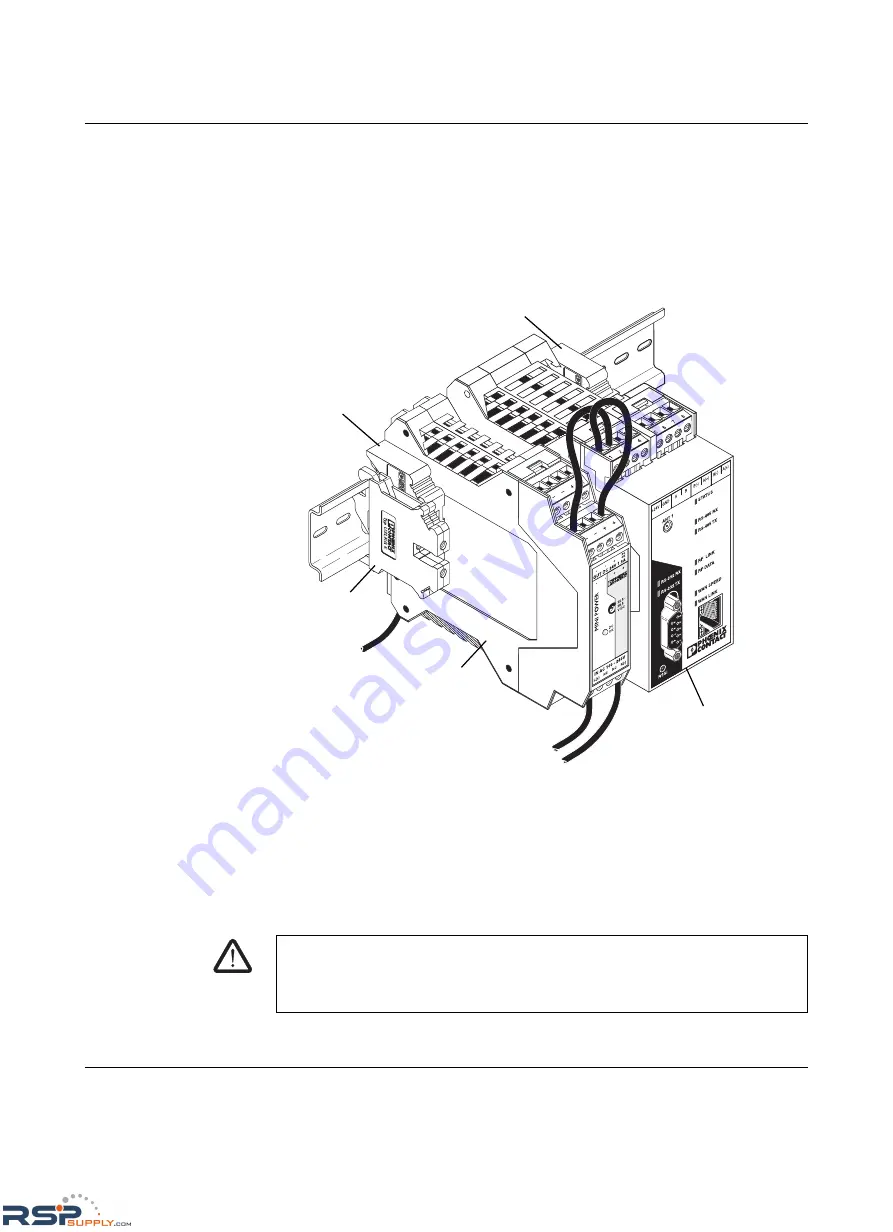
Figure 3-1 shows a typical RAD-ISM-900-EN-BD… radio installation using a Phoenix
Contact power supply, end clamps and a grounding block.
Figure 3-1
Typical installation
When mounting the radio on a standard 35 mm mounting rail, end clamps should be
mounted on both sides of the module(s) to stop the modules from slipping on the rail (see
Figure 3-1).
Modules are installed from left to right on the mounting rail. Install modules to mounting rail
as described in the following steps.
RAD-ISM-900-EN-BD
FLBL-2938-03R2
Transmit
Receive
Po
wer
RF Link
To protective
Earth Ground
Ground
terminal
block
To power
source
Power
supply
End bracket
End bracket
RAD-ISM-900-EN-BD…
WARNING:
Never install or remove a module while power is applied to any component on the rail.
Before installing or removing a module, disconnect power to the entire station. Make sure
work on the entire station is complete before switching power back on.
RSPSupply - 1-888-532-2706 - www.RSPSupply.com
http://www.RSPSupply.com/p-12970-Phoenix-Contact-2900016-Radio-900-MHz-Ethernet-Radio.aspx


