


5756B
63
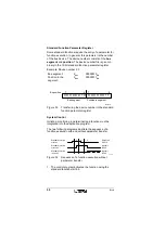
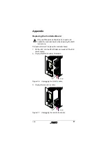
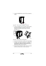
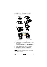
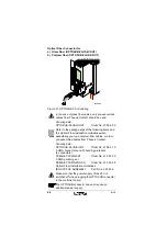
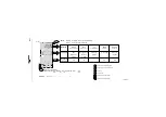
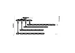
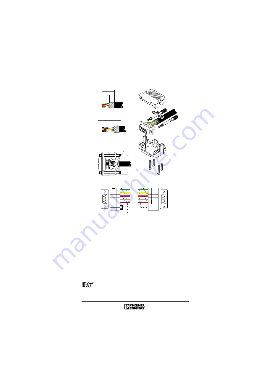
Remote Bus Connector With Solder Connection
Designation: IBS DSUB 9/L, Order No. 27 58 47 3
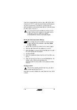
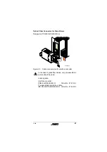
Figure 44
D-SUB connector cabling
1. Strip 20 mm off the cable sheath, and shorten the braided
shield to 8 mm.
Strip 3 mm off the wire ends, and connect the signal lines
in accordance with the drawing.
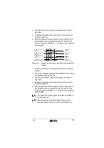
2. Fold the braided shield back over the cable sheath.
3. Clamp the shield under the strain relief, so that a
conductive connection to the metal-plated connector
housing is created.
Use only the metal-plated connectors recommended
by Phoenix Contact.
2 0 m m
( 0 . 7 9 i n . )
8 m m ( 0 . 3 2 i n . )
3 m m ( 0 . 1 2 i n . )
9 - p o s . D - S U B
m a l e c o n n e c t o r
9 - p o s . D - S U B
f e m a l e c o n n e c t o r
R e m o t e b u s c a b l e ( D 9 / D 9 )
g r e e n
p i n k
y e l l o w
g r a y
b r o w n
S o l d e r
s i d e
S o l d e r
s i d e
D O
D I
C O M
6
1
7
2
3
D I
D O
S t r a i n
r e l i e f
9
6
1
7
2
3
5
D O
D I
C O M
D I
D O
S t r a i n
r e l i e f
1
2
3
S t r a i n r e l i e f
5 4 6 9 A 0 3 5
1
5
6
9
1
5
6
9


