


12
5756B
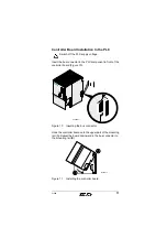
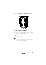
Lock the controller board to the mounting rail using the two
slotted-head screws at the bottom of the board.
Figure 12
Locking the controller board
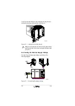
Make sure that the bus connector makes good contact
and the controller board is securely placed and locked
in the PLC.
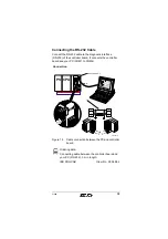
Connecting the External Supply Voltage
Connect the external supply voltage according to the
following diagram.
Figure 13
Connecting the supply voltage
5 7 5 6 A 0 1 3
5 7 5 6 A 0 1 4
0 V
2 4 V
I
N T E R
B
U S
I B S S 7 3 0 0 D S C - T
O r d . N o . : 2 7 1 9 9 7 5
C P U
S T O P
7
6
5
4
3
2
1
0
7
6
5
4
3
2
1
0
P S


