18
5756B
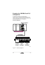
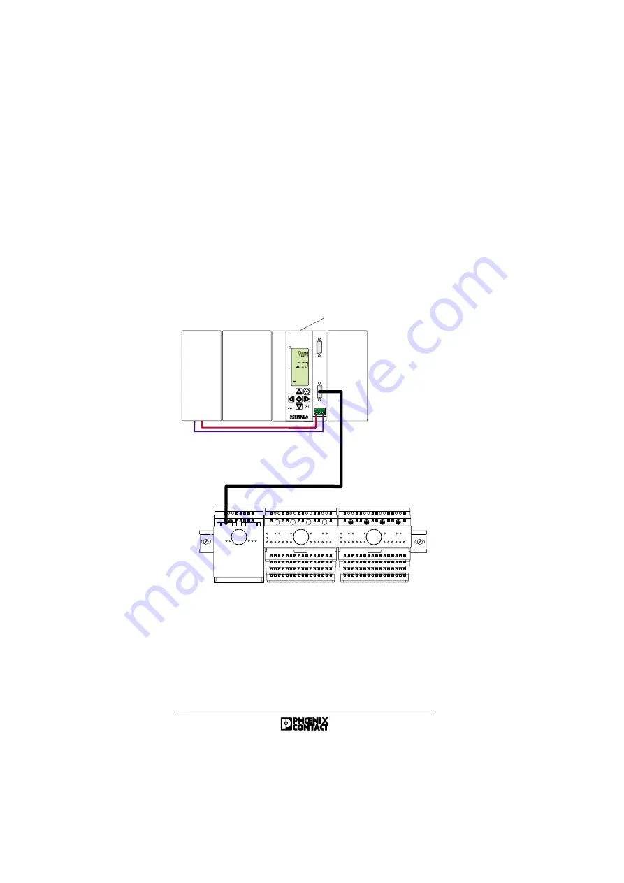
Example of an INTERBUS and PLC
Configuration
To make your introduction to working with the
IBS S7 300 DSC-T controller board as straightforward as
possible, the descriptions in later sections are based on the
following INTERBUS and PLC configuration.
Example Configuration
Figure 17
Example configuration
F E
F E
F E
F E
F E
B u s t e r m i n a l
m o d u l e
I B S T 2 4 B K - T
I D : 8 ( 8 h )
1 6 d i g i t a l
i n p u t s
I B S T 2 4 D I 1 6 / 4
I D : 1 9 0 ( B E h )
1 6 d i g i t a l
o u t p u t s
I B S T 2 4 D O 1 6 / 3
I D : 1 8 9 ( B D h )
2
1
3
5 7 5 6 A 0 1 8
I B S S 7 3 0 0 D S C - T
C P U
I N
I
N T E R
B
U S
I B S S 7 3 0 0 D S C - T
O r d . N o . : 2 7 1 9 9 7 5
S T O P
7
6
5
4
3
2
1
0
7
6
5
4
3
2
1
0
P S
I N T E R B U S


