
36
5756B
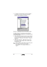
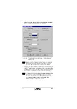
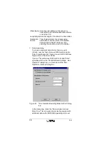
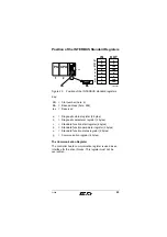
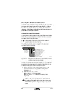
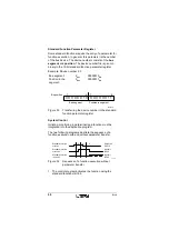
In the example the base address of the controller board is
address 256. The address of the input data word (16-bit input
module for the INTERBUS) is DB2.DBB0 and the address of
the output data word (16-bit output module for the
INTERBUS) is DB3.DBB0.
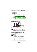
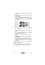
If your bus configuration does not correspond to the
example bus configuration, parameterize your bus
configuration and allocate the addresses for input and
output data in accordance with the example. Please
note that the default setting in the "Controller Board
Settings... IBS Data Records" dialog box is "E" for the
input area and "A" for the output area. Following the
example the data blocks (DB) must be set as input /
output areas.
2. After formatting the parameterization memory, save your
configuration there.
3. Switch the power supply to the S7-300 PLC off and back
on (POWER-UP). The controller board transfers the
current data from the parameterization memory and
enters RUN state, if the configuration was parameterized
following the instructions. In case of error please check
you configuration.
4. Call your STEP 7
®
programming package and load the
IOASYNCH.S7P example file.
5. Perform an overall reset of the S7 CPU.
6. Load the hardware configuration for the example (see
Figure 28 on page 35) as described in "Integration of the
Controller Board in STEP 7®" on page 19 into the PLC.
7. Load the example project to the PLC.
8. Start the PLC.
The data from the INTERBUS input or output modules is
available to you in the data record parameterized in
IBS CMD.
If the input data can be seen on your output module
(displayed by the LEDs on the module), you have started PLC
and INTERBUS operation without error.
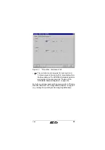
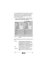
Input data word
DB2.DBW0
Output data word
DB3.DBW0


