EN 12
7.
MCP9350i
Installation and Initial Checks
7.
Installation and Initial Checks
7.1. Installation
1.
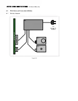
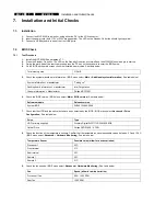
Connect the MCP9350i to a monitor, using either the DVI or the VGA connector.
2.
Insert the power cord (both 110V or 230V are supported). The LED on the Standby-On button should light-up yellow.
3.
Connect a USB keyboard to one of the front USB ports.
7.2. BIOS
Check
7.2.1. Test
Procedure
1.
Install the MCP9350i. See paragraph 7.1.
2.
Press the Standby-On button. The LED on the Standby-On button will turn-off and the MCP9350i should begin to start up.
3.
During the early part of the start-up process press the ‘F2’ key on the keyboard to enter the BIOS setup.
4.
On the BIOS setup main screen check the installed memory size. See table below.
Total memory size
512 MB
5.
Check the system manufacturer information. (BIOS menu select:
Main
>
Additional system information
). See table below.
System information > manufacturer
“Tatung co.”
Desktop board information > manufacturer
Intel Corporation
Chassis Information > Manufacturer
Philips MCPC1001
6.
Check the BIOS version. (BIOS menu select:
Main
>
BIOS version
). See table below.
Software module
Release version
System BIOS
SU94510J.86A.0048
7.
Check that the HDD and the optical drive have been detected by the BIOS. (BIOS menu select:
Advanced
>
Drive
Configuration
). See table below.
Drive Type
HDD (primary supplier)
Western Digital WD????JS-55M-250.0GB
Optical Drive
Philips DVDR1628 – ATAPI
8.
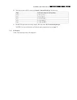
Check the function of the temperature sensors. Confirm that the temperatures have reasonable values, between 0 C and 128 C.
(BIOS menu select:
Advanced
>
Hardware Monitoring
). See table below.
Temperature Sensor
Possible value (allow for a wide variation)
Processor 1
63 C
Front internal
31 C
Rear internal
25 C
Remote 1
23 C
Remote 2
21 C
9.
Check the fan speeds. (BIOS menu select:
Advanced
>
Hardware Monitoring
). See table below.
Fan
Speed (allow for a wide variation)
Processor 1 fan
900 – 1400 RPM
Rear fan
1000 RPM


