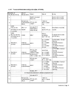
During encode operation the output ports P2.5, P2.6 and P2.7 are controlled by the
microprocessor. The outputs from these ports are combined by the summing network
consisting of R267, R268 and 8269. This signal is then integrated and filtered by IC205d and
its associated components. The output of IC205d is then coupled via C263, R323 and R390 to
the final transmit audio summing amplifier IC210.
3.2.4.9
CTCSS AND REVERSE TONE BURST
IC204 located on the control PCB, is the CTCSS encoder/decoder device. When this option is
fitted R249 is removed and the receiver audio signal path is passed via IC204 at PINS 23 and
19. The audio output at PIN 19 is high pass filtered by IC204, to remove frequencies below
300Hz. This ensures that received signals containing the sub-audible tones have the tones
removed to prevent unnecessary residual hum at the loudspeaker.This audio path through
IC204 is muted until a tone is successfully detected or the microprocessor provides an unmute
command to IC204.
The audio input at PIN 23 of IC204 is also processed to decode the CTCSS tone. When a
tone is successfully decoded the output at PIN 13 is switched to a logic low, and the received
audio is passed.
A microprocessor command changes IC204 from decode to encode when the PTT is activated
on a CTCSS channel. The encode tone output appears at PIN 16 at a level of approximately
775mV rms. The encode tone output has two alternate paths before being combined with the
transmitter audio at PIN 13 of IC210. One path passes via C243 and the CMOS switch IC212
to the encode level setting potentiometer R354. The alternate path is via transistors TR230
and TR231. This circuit provides the -120 deg RTB feature. The passive network of C241,
C242, R344 and R345 produces approximately 60 deg phase lag. TR231 provides a further
180 deg and this combination results in a total of 120 deg lag. During a transmission the
encoder tone output passes via C243 to PIN 1 of IC212. The output appears at PIN 2 and 3.
Microprocessor control sets IC212 PINS 13 and 6 to logic high. At the release of PTT, IC212
PINS 13 and 6 are switched low by the microprocessor and the encode tone is passed via the
phase shift network to PIN 4 of IC212 and this signal now appears at PINS 2 and 3 of IC212.
An alternative 180 deg RTB is available directly from IC204 output. When 180 deg RTB option
is required the microprocessor provides IC204 with a serial command to produce a 180 deg
phase shift in the encode tone. In this option the encode output is passed via C243 and IC212
but the -120 deg phase shift network is never activated.
3.2.5
Front Panel
3.2.5.1
9-CHANNEL FRONT PANEL
The visual information is displayed on the Liquid Crystal Display LCD 1. A seven-segment
symbol may display up to channel digit number 9. Other visual indicators are as follows:
Receiver Busy
Transmit
Selcall (call or called)
Section 3 Page 26


