4.5
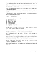
THE PROCEDURE
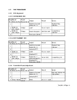
4.5.1
VCO Alignment
4.5.1.1 VHF RECEIVE VCO
Step
No
Result
Measured by
Result
Measured at
Adjust
Result
Notes
1
Switch on power
Select ch. 3..
Highest freq.
channel.
2
DVM, dc
volt, range
TP402
L407
15.0 +10.2V
3
DVM, dc
volt. range
TP402
Select channel 1 3.OV to 5.OV
Lowest freq.
channel.
4
Disconnect DVM.
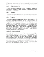
4.5.1.2 VHF TRANSMIT VCO
Step
No
Result
Measured by
Result
Measured at
Adjust
Result
Notes
1
Switch on power.
Select ch. 3.
Highest freq.
channel
2
Activate PTT.
3 DVM, dc
volt. range.
TP402
L445
15.0 -/+ 0.2V
4
Disable PTT
5
DVM, do
volt. range
TP402
Select ch. 1
and activate PTT
3.0 to 5.0V
Lowest freq. ch.
6
Disable PTT
Disconnect DVM
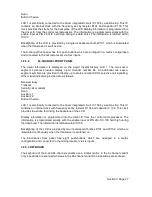
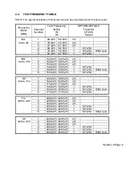
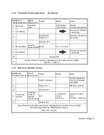
4.5.2
Transmitter Power Adjustment
Step
No
Result
Measured by
Result
Measured at
Adjust
Result
Notes
1
Switch on power.
Select ch. 2.
Mid freq channel for
high power
2
Activate PTT
3 Power Meter Antenna
socket
R581
25.0 -/+ 1 watt
Section 4 Page 4


