4.5.4
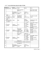
UHF Receiver Front End Alignment
Step
No
Result
Measured by
Result
Measured at
Adjust
Result
Notes
1
Switch on power
and select channel
1.
Lowest freq. channel.
2
Antenna
socket SK402
RF sig. gen.
output..
50uV pd level
and freq. for
channel 1.
Modulate generator
with 1 kHz at 60% of
max. dev.
3
CRO,
5mV ac per div.
10uSec per div.
10x probe.
PIN 2 of
U401
R554
Maximum level
on CRO.
Typ. 180mV p-p.
Sets tracking offset
adjustment.
4
Select ch. 3
Highest freq. channel.
5
RF sig. gen. output. Freq. of channel
3
6
CRO
5mV ac per div
10uSec per div.
10x probe.
PIN 2 of
U401
R557
Maximum level
on CRC.
Typ. 200mV p-p.
Sets tracking gain
adjustment.
7 REPEAT STEPS 1 TO 6 TO ELIMINATE SLIGHT INTERACTION BETWEEN R554 AND R557.
8
Select ch. 3
Highest freq. channel
g
RF sig. gen.
output.
1 mV pd level,
and freq. of
channel 3.
10
AF level
meter.
Speaker
output at
S K202.
Volume
control.
300mW in
4ohm.
11
AF level
meter.
Speaker
output at
SK202.
L404
Max. AF
level.
Re-adjust volume
for 300mW output
when L404 is peaked
12
Distortion
meter.
Speaker
output at
SK202.
L404
Less than 3%
Slight re-adjustment
of L4'04 may be
necessary
13
RF sig. gen.
output.
0.31 uV pd
level.
14 SINAD meter
Speaker
output at
SK202.
Greater
than 12dB
SINAD.
Verifies alignment
Section 4 Page 6


