Disassembly Procedures (A1)
68
Chapter 6 - Disassembly Guide
Caution
During reassembly, pay particular attention to the polarity
of the battery cable before reattaching. The polarity is
marked on the circuit board. Red connects to the +ve
terminal, black connects to the –ve terminal. If battery cable
polarity is reversed, it is likely that circuit damage will
occur.
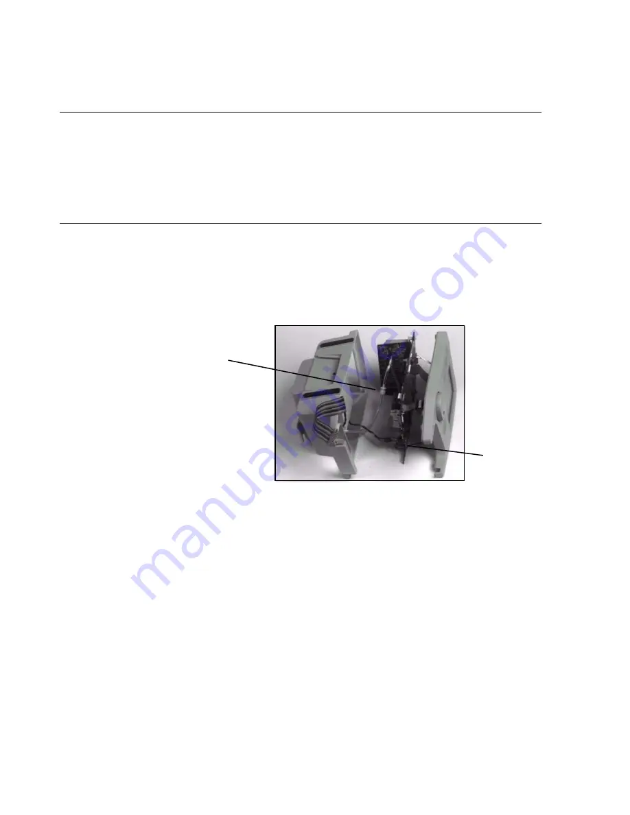
7. Unscrew the NiBP Luer connector.
During reassembly, preload the NBP Luer connector by twisting the
silicone NBP tubing in opposite directions prior to making the Luer
connection. This prevents disconnection.
Front and rear case assemblies are now completely separate from one another.
Front Case Disassembly Procedures
This section describes how to remove/replace items from the front case
assembly. First separate the front and rear assemblies as described in the
section “Separation of Front and Rear Case Assemblies” on page 78.
Procedure to remove the main PCB assembly from the front case
assembly:
1. Use a Phillips-head screwdriver to remove the screw holding the main
PCB assembly in place in the front cover assembly.
For reassembly, note the two guides in the cover and the corresponding
two notches in the PCB.
Luer connector
to NiBP pump
tubing
Battery
cable
Summary of Contents for M3921A
Page 12: ...xii Contents ...
Page 16: ...Related Documents 4 Introduction ...
Page 48: ...Safety Tests 36 Performance Verification ...
Page 72: ...Troubleshooting Guide 60 Chapter 5 Troubleshooting ...
Page 100: ...Disassembly Procedures A3 88 Chapter 6 Disassembly Guide ...
Page 103: ...Top Level Assembly Chapter 7 Spare Parts 91 Figure 2 A1 Top Level Assembly Drawing 2 of 2 ...
Page 105: ...Top Level Assembly Chapter 7 Spare Parts 93 Figure 3 A3 Top Level Assembly Drawing ...
Page 108: ...Front Case Assembly 96 Chapter 7 Spare Parts Figure 5 A1 Front Case Assembly Drawing 2 of 3 ...
Page 110: ...Front Case Assembly 98 Chapter 7 Spare Parts Figure 7 A3 Front Case Assembly Drawing 1 of 2 ...
Page 111: ...Front Case Assembly Chapter 7 Spare Parts 99 Figure 8 A3 Front Case Assembly Drawing 2 of 2 ...
Page 114: ...Rear Case Assembly 102 Chapter 7 Spare Parts Figure 9 A3 Rear Case Assembly Drawing 1 of 3 ...
Page 115: ...Rear Case Assembly Chapter 7 Spare Parts 103 Figure 10 A3 Rear Case Assembly Drawing 2 of 3 ...
Page 116: ...Rear Case Assembly 104 Chapter 7 Spare Parts Figure 11 A3 Rear Case Assembly Drawing 3 of 3 ...
Page 124: ...Repacking In A Different Carton 112 Chapter 8 Packing For Shipment ...
Page 144: ...Preventative Maintenance 132 Chapter 10 Training Program ...
Page 150: ......


