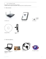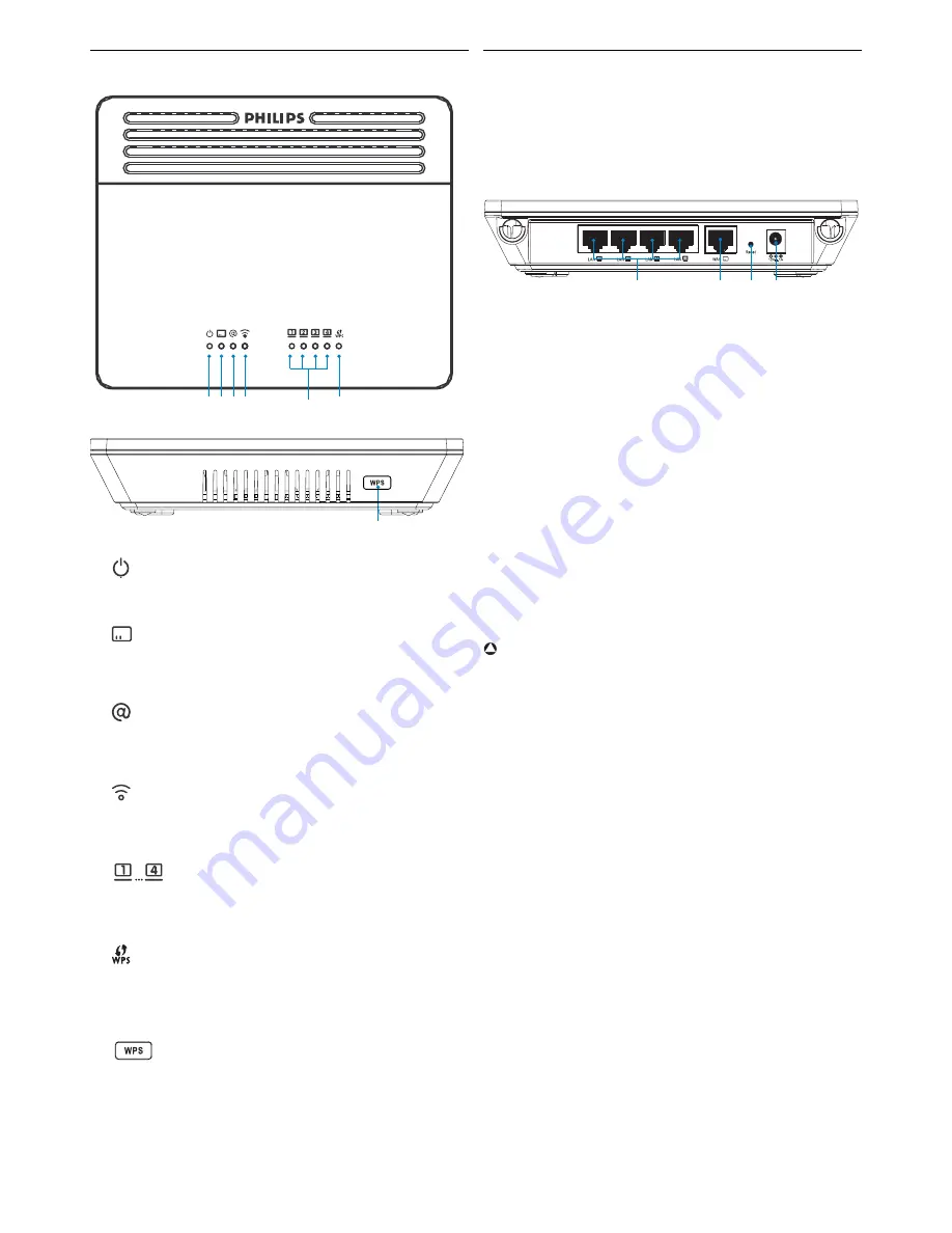
Your Wireless Router
4
2.3
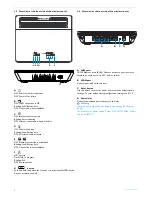
Overview of the front side of the wireless router
A
ON: Power on, normal operation
OFF: Power off or failure
B
ON: WAN connection is OK
Blinking: Send/Receive data
OFF: Connection is not established
C
ON: Internet connection is up
Blinking: data transfering
OFF: Internet connection is down or failure
D
ON: Wireless link is up
Blinking: Send/Receive data
OFF: Wireless disable or failure
E
ON: Ethernet connection is established
Blinking: Send/Receive data
OFF: Connection is not established
F
ON: Success
Flash Flash: In progress
Blinking: Fail
OFF: No connection
G
button
Push and hold this button for 3 seconds to install another WPS device
on your network, see 4.6.4
2.4
Overview of the rear side of the wireless router
A LAN ports
10/100 Ethernet ports (RJ-45). Connect devices to your local area
network on these ports (i.e. a PC, hub, or switch)
B WAN port
Connect your modem to this port
C Reset button
Use this button to reset the power and restore the default factory
settings. To reset without losing configuration settings, see 4.11.3
D Power Inlet
Connect the included power adapter to this inlet
Warning
Using the wrong type of power adapter may damage the Wireless
Router.
For use only with power supply "Leader: MU12-2120100-B2" and/or
"Jentec: AH1212-C".
A B C D
F
E
G
A
C
D
B
!


