background image

Page 9

BaLaNCe POiNt aNd CONtrOL tHrOWs

  ailerons: 

30mm (1-3/16") up  and  down

  elevator: 

25mm (1") up  and  down

  rudder: 

50mm (2") right  and  Left

sport flying

  ailerons: 

as Much as Possible up  and  down

  elevator: 

as Much as Possible up  and  down

  rudder: 

as Much as Possible right  and  Left

3d flying

  ailerons: 

30%

  elevator: 

30%

  rudder: 

30%

sport flying

3d flying

  ailerons: 

40%

  elevator: 

40%

  rudder: 

40%

Exponential 'softens' the response of the control surfaces around the neutral stick position. This makes the aircraft easier to control 
while using such large control throws. The Exponential values shown are given as a percent. Please note that different brands of radio 
control systems may call for + or - Expo. Please check your transmitter's owners manual for more info.

THE CONTROL THROWS ARE MEASURED FROM THE WIDEST POINT OF THE CONTROL SURFACES

the Centre of Gravity (C/G or Balance Point) is 95mm (3-3/4") back from the leading edge of the tOP wing, measured at 
the sides of the fuselage.

BaLaNCe POiNt

WARNING

  For test flying and general sport flying, we suggest you balance the aircraft at the C/G recommended above. For 3D 

flying, you may want to experiment moving the C/G back in small increments until you're satisfied with the result.

CONtrOL tHrOWs

 exPONeNtiaL

To ensure great flight performance and to be able to trim your aircraft properly, it is critical that you adjust the motor thrust as 
necessary. When set properly, the trim for the elevator and the rudder should be neutral. Fine-tune the down-thrust and right-thrust 
amounts until this neutral trim is achieved.

MOtOr tHrust

q

  For the stick mount, carefully trim the end of the motor mounting 

stick at a slight angle, so that the motor will have approximately 
2º of down-thrust and right-thrust.

q

  For the radial mount, add a thin washer between the top and 

right side of the motor mount and mounting plate, so  the motor 
will have approximately 2º of down-thrust and right-thrust.

PrefLiGHt CHeCK aNd safety

l

  Check the operation of the throttle. Double-check that you're getting full power when the throttle control stick is at full.

+

  If you're using a computer radio, you may need to increase your throttle channel's EPA setting to result in full power. (Refer to    

your radio system's operating guide for further information.)

l

  Check the condition of the transmitter batteries. They should be fully charged.

l

  Check every glue joint in the aircraft to ensure that everything is tight and well-bonded.

Summary of Contents for Quick Time

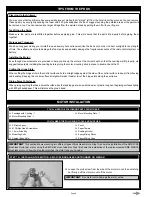
Page 1: ... Brushless l Battery Required 3 Cell 900mAH Li PO Made in China All Contents Copyright 2007 Phase 3 Models Version 1 April 2007 All Rights Reserved Phase 3 Models P O Box No 402 Texaco Road PO New Territories Hong Kong Please refer to the separate sheet included with your kit for Customer Service Information CUSTOMER SERVICE INFORMATION specifications l EPP sheet foam open frame construction l Ext...

Page 2: ...heck boxes next to each procedure After you complete a procedure tick the box This will help prevent you from losing your place l Cover your work table with brown paper or a soft cloth both to protect the table and to protect the parts l Keep a couple of small bowls or jars handy to put the small parts in after you open the accessory bags l We re all excited to get a new aircraft in the air but ta...

Page 3: ...KMS KBM 31 08 Brushless Outrunner Motor QTY 1 KMS 18Amp Brushless ESC QTY 4 Cirrus CS301 Micro Servos QTY 1 APC 10 x 3 8 Slow Flyer Propeller QTY 1 Impulse Power 3C 900mAH Li PO Battery QTY 1 ProPeak Quattro Li PO Charger QTY 1 KMS Stick Mount Adapter for KMS Outrunner Motors QTY 2 305mm 12 Servo Extensions QTY 1 Y Lead QTY 1 Xtra 2mm Gold Connector Set QTY 1 Double Sided Tape QYT 1 Velcro Hook an...

Page 4: ...light or in a hot car or storage area l Do NOT get wet or expose to moisture l Do NOT short circuit the battery l ONLY discharge and charge the battery outdoors or in a firesafe container l Do NOT charge with reverse polarity l Do NOT leave the battery connected when not in use l Do NOT operate or charge unattended l Do NOT solder to the battery directly and do not get the battery hot in any way L...

Page 5: ...ers q Z Bend Pliers q Needle Nose Pliers q Modelling Knife q Scissors q Electric or Hand Drill q Assorted Drill Bits q Straight Edge Ruler q Pencil q T Pins q Set Square q 220 Grit Sandpaper with Sanding Block q Masking Tape q Paper Towels q Rubbing Alcohol q Epoxy Mixing Sticks q Epoxy Mixing Cups q Soldering Iron q Solder q Heat Shrink Tubing Assorted Sizes q Heat Gun for Heat Shrink Tubing KIT ...

Page 6: ...inge slots in the control surfaces hold a straight edge against the side of the control surface to keep it from flexing and bending Keeping the control surface straight will make it easier to cut the hinge slots along the centreline Gluing Smooth Surfaces When gluing anything that has a smooth surface like the landing gear wire pushrod wire or plastic roughen the gluing surfaces lightly with 220 g...

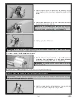
Page 7: ...your motor using the screws provided with your motor IMPORTANT Before test fitting and mounting the motor in the next few procedures make sure that you install the motor mounting stick so that the motor is towards the bottom of the fuselage q Slide the motor mounting stick assembly into the moulded channel in the fuselage When positioned properly the back edge of the propeller should be 121mm 4 3 ...

Page 8: ...e into the fuselage IMPORTANT Before test fitting and mounting the motor in the next few procedures make sure that you install the motor mounting plate assembly so that the motor is towards the top of the fuselage q Install your motor onto the motor mounting plate using three wood screws not included PRO TIP After flying the aircraft you may want to add right and or down thrust to the motor You ca...

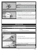
Page 9: ... wing at the trailing edge using the centreline joint on the bottom of the wing as a guide q Measure out 25mm 1 to the right and to the left of the centreline mark C L and draw two more marks A IMPORTANT Again these two outer marks represent the sides of the fuselage and will be used to centre the wing q Slide the wing into the fuselage and line up the two outer marks at both the leading edge and ...

Page 10: ... 5 minute epoxy to glue them into place works better than C A The 5 minute epoxy allows a longer working time too which makes it easier to line up the control surfaces and hinge them properly q Look from the front of the aircraft at both the wing and the stabiliser When aligned properly the stabiliser should be parallel to the wing IMPORTANT It might be necessary to trim down one side of the stabi...

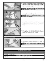
Page 11: ... hold the aileron in place until the epoxy cures q After the epoxy has cured pivot the aileron up and down several times to ensure free hinge movement then repeat the previous procedures to hinge the second aileron to the other half of the wing Step 2 hinging THE elevator q Carefully cut four hinge slots in the leading edge of the aileron at the marks that you drew then cut four hinge slots at the...

Page 12: ...o place using the same techniques that you used to cut the hinge slots and glue the hinges into the ailerons and the elevator Allow the epoxy to cure before proceeding q Cut the corresponding hinge slots into the back of the fuselage then hinge the rudder to the fuselage using the same techniques that you used to hinge the elevator to the stabiliser Remember once the epoxy has cured pivot the rudd...

Page 13: ...tall the control horn backplate The control horn will mount directly to the plywood elevator support plate q 5 Minute Epoxy q Thin C A q 0 and 1 Phillips Head Screwdrivers q Wire Cutters q Z Bend Pliers q Needle Nose Pliers q Modelling Knife q Electric or Hand Drill q Pushrod Wires 3 q Plastic Control Horns 6 q Plastic Clevises 4 q Wood Screws 12 q 1 6mm 1 16 Drill Bit q Ruler q Pencil q 220 Grit ...

Page 14: ...nd the end of the pushrod wire to roughen the surface so that the glue will stick to it when you install the clevis q Double check that both the elevator and the servo arm are still centred then slide one clevis over the end of the pushrod wire and snap it into the outermost hole in the control horn q Glue the clevis to the pushrod wire using a couple of drops of thin C A q Remove the backplate fr...

Page 15: ... or else you ll crush the foam q Make a Z Bend and a V Shaped bend in the second pushrod wire then install the servo arm onto the rudder servo using the same techniques that you used to install the servo arm onto the elevator servo IMPORTANT The servo arm should point toward the top of the fuselage and the pushrod wire should be installed in the outermost hole in the servo arm q Install the pushro...

Page 16: ...rfaces are centred If necessary you can centre them by adjusting the width of the V Shaped bend in each of the pushrod wires Use a pair of needle nose pliers to make your adjustments Opening the bend will lengthen the pushrod and closing the bend will shorten the pushrod The servo arms should point down towards the wing and the pushrod wires should be installed into the outermost hole in the servo...

Page 17: ... Step 2 Installing the WHEELS FINAL ASSEMBLY You ll Need the following TOOLS AND SUPPLIES q Run the aerial out the side of the fuselage and secure it along the side of the fuselage using pieces of clear tape not included Do not cut the aerial shorter Allow the excess to hang beyond the back of the fuselage IMPORTANT Apply a dab of epoxy to the plywood wheel retainers to secure them to the axles Be...

Page 18: ...s of clear tape not included to secure the cowling into place q Double check that you can remove and install the battery easily through the bottom of the cowling Adjust the cutout in the bottom of the cowling if necessary This completes assembly Please refer to the next page for information on balancing control throws exponential and motor thrust settings q Mount the battery to the bottom of the b...

Page 19: ...nt to experiment moving the C G back in small increments until you re satisfied with the result control throws Exponential To ensure great flight performance and to be able to trim your aircraft properly it is critical that you adjust the motor thrust as necessary When set properly the trim for the elevator and the rudder should be neutral Fine tune the down thrust and right thrust amounts until t...

Page 20: ...our first few flights l Check to ensure that all of the control surfaces are moving the proper amount in both low and high rate settings l Check the receiver aerial It should be fully extended and not coiled up inside the fuselage Do not cut the receiver aerial shorter or the range of your radio control system will be greatly reduced l You should complete a successful range check of your radio equ...

Reviews: