


Adjustment
77
Fig. 13 - 16
64-072
2
3
1
13
.18
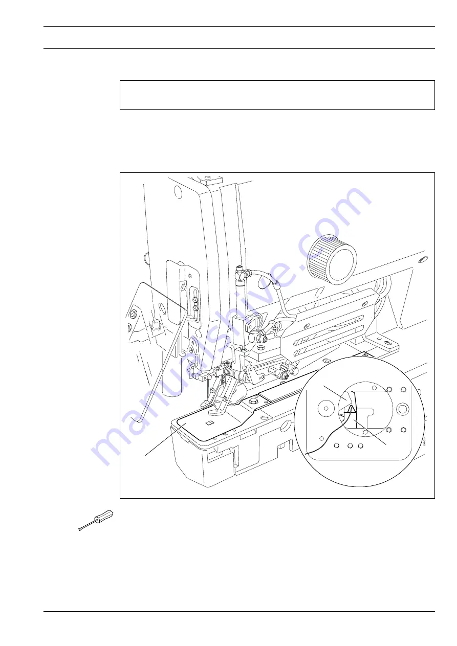
Manual cutting test
Requirement
In a manual cutting operation the thread should be cut reliably.
●
Dismount cloth plate
1
and needle plate insert.
●
Place the thread between thread catcher
2
and knife
3
.
●
Disconnect the machine from the pneumatic power supply.
●
Check the
requirement
by carrying out a manual cutting operation.
●
Mount the needle plate, taking care to see that the spherical head of the cutting
cylinder grips into the corresponding guide section of the needle plate.
Summary of Contents for 3307-1 SERIES
Page 127: ...127 Circuit diagrams Version 13 11 06 91 191 512 95 Teil 1...
Page 128: ...128 Circuit diagrams Version 13 11 06 91 191 512 95 Teil 2...
Page 129: ...129 91 191 512 95 Teil 3 Version 13 11 06 Circuit diagrams...
Page 130: ...130 Circuit diagrams Version 13 11 06 91 191 512 95 Teil 4...
Page 131: ...131 91 191 512 95 Teil 5 Version 13 11 06 Circuit diagrams...


