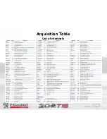
Acquisition Table
List of channels
Channels
Unité
Description
Channels
Unité
Description
Channels
Unité
Description
Advance
°crk
Ignition advance
I_H6_THR_INJ
A
Throttle body and pedal current
Steer_A
°
Steering wheel position
AX_SRG
g
Longitudinal acceleration
I_H7_WPump
A
Water pump current (2)
Steer_S
°/s
Steering wheel speed
AY_SRG
g
Lateral acceleration
I_H8_HBeam
A
High beam headlight current
SW_Gravel
Gravel switch state
AZ_SRG
g
Vertical acceleration
I_H9_FOG_F
A
Front fog lights current
SW_Power
Power switch state
BangSts
ALS status
I_L1_DiffFan
A
Rear diff radiator fan current (1)
SW_Road
Road / Stage switch state
Barrel
Volt
Barrel position, calculated from track 1 and 2 (Barrel1 and
Barrel2)
I_L10_Aux
A
Auxiliary connector current
SW_S1
Throttle switch state
Barrel1
Volt
Barrel position, measured from track 1
I_L11_Marker
A
Beacon current
SW_S2
Throttle switch state
Barrel2
Volt
Barrel position, measured from track 2
I_L12_Stop3
A
3rd stop light current
SW_Tarmac
Tarmac switch state
BRK_DiagLC1
Diagnostic for high current BRK output
I_L2_DiffFan
A
Rear diff radiator fan current (2)
T1
°C
Air temperature in the filter box
BRK_DiagLC2
Diagnostic for low current BRK output
I_L3_Horn
A
Hron current
T2
°C
Air temperature in the inlet manifold
BRK_Fonct
State of the BRK outputs
I_L4_Indic_R
A
Right blinker current
T4
°C
Exhaust gaz temperature
BRK_SW
State of the BRK switches
I_L5_Indic_L
A
Left blincker current
TBoxuActCorr
°C
ECU processor temperature
Cmd_Up
Upshift procedure ON
I_L6_PosLight
A
Position light current
TBoxuTlmCorr
°C
ECU processor temperature
Conso
L
Fuel consumption since the last zero
I_L7_Reverse
A
Reverse light current
TDiff_R
Ohms Rear diff oil temperature
DDU_Page
Page
Number or name of the page displayed
I_L8_FOG_R
A
Rear fog light current
TGearbox
°C
Gearbox oil temperature
DiagAcqAna0
Sensors diagnostic
I_L9_Stop
A
Stop light current
Throttle
%
Throttle body position, calculated from track 1 and 2 (body1 and
body2)
DiagAcqAna1
Sensors diagnostic
IGN_Lim
rpm
Ignition limitor
Throttle_Tgt
%
Throttle body target
DiagAcqAna2
Sensors diagnostic
INJ_Lim
rpm
Injection limitor
Throttle1
%
Throttle body position, measured from track1
DiagTeam
Sensors diagnostic
KnDeton1
mV
Knock level for cylinder 1
Throttle2
%
Throttle body position, measured from track2
Distance
m
Total distance
KnDeton2
mV
Knock level for cylinder 2
TOil
°C
Engine oil temperature
DistanceLap
m
Distance for the considered lap
KnDeton3
mV
Knock level for cylinder 3
TOption
°C
Front brake pads temperature
DistanceStage
m
Total distance in stage mode
KnDeton4
mV
Knock level for cylinder 4
TurboSts
Turbo close loop state
FlagCoilOC
Diagnostic open circuit - coil
KnockMild
Mild knock
TWater
°C
Cooling circut temperature
FlagCoilSC
Diagnostic short cut - coil
KnockStrong
Strong knock
USB_Status
State of the map update via the USB key
FlagInjOC
Diagnostic open circuit - injector
NTurbo
Krpm
Trubo rev
Vbatt
volt
Battery voltage
FlagInjSC
Diagnostic short cut - injector
P1
mbar
Air pressure in the filter box (after filter)
Vref1Corr
V
Reference power supply for sensors (1)
Gauge
Fuel level measured by the gage (not precise)
P2
mbar
Air pressure in the inlet manifold
Vref2Corr
V
Reference power supply for sensors (2)
GDU_OutLed
State of the gearbox display leds
P2P
mbar
Air pressure before the throttle body
Vref3Corr
V
Reference power supply for sensors (3)
Gear
Gear
PAccu
bar
PEAL accumulator pressure
Vref4Corr
V
Reference power supply for sensors (4)
HB1_Diag
Diagnostic of the trhottle body (40 = OK, 49 = OC, 61 = SC)
Pbrake_F
bar
Front brake pressure
VRS_Diag
Synchronization diagnostic
HPPump_Cmd
°crk
Fuel pump command
Pbrake_R
bar
Rear brake pressure, before the handbrake
VRS_Status
State of the synchronization
HPPump_Diag
Diagnostic of the HP fuel pump (0 = OK, 1 = error)
PEAL_Cmd
Command of the PEAL solenoid valve
VVT1_Cmd
%
VVT command
HPPump_Targe
t
bar
Fuel pressure target
Pedal
%
Throttle pedal position, calculated from track 1 and 2 (Pedal1 and
Pedal2)
VVT1_Diag
VVT diagnostic
I_H1_WPump
A
Water pump current (1)
Pedal1
%
Throttle pedal position, measured from track1
VVT1_Err
°crk
VVT position error
I_H10_Inner
A
Inner light pods current
Pedal2
%
Throttle pedal position, measured from track2
VVT1_ShiftCam1
°crk
VVT position, measured for the 1st tooth of the VVT crank wheel
I_H11_Outer
A
Outer light pods current
PedalLearnState
State of the throttle/pedal learning state
VVT1_ShiftCam2
°crk
VVT position, measured for the 2nd tooth of the VVT crank wheel
I_H12_LBeam
A
Low beam headlight current
PFuelHP
bar
Fuel pressure in the injectors ramp
VVT1_ShiftCam3
°crk
VVT position, measured for the 3rd tooth of the VVT crank wheel
I_H13_EVs
A
EV current (Waste Gate, VVT and PEAL)
PHandBrake
bar
Rear brake pressure, after the handbrake
VVT1_TgtFilt
°crk
VVT position target
I_H14_Radio
A
Radio connector current
POil
bar
Engine oil pressure
WG_N_Tgt
Krpm
Turbo rev target
I_H15_Heater
A
Heater current
PWater
bar
Cooling circuit pressure
WG_P_Tgt
mbar
Air compressed pressure target
I_H16_FuelPu
mps
A
MP fuel pump and feed pumps current
Qinj
mg
Fuel injected quantity
WG_RCO
%
Turbo wastegate commande
I_H17_PEAL
A
PEAL motor current (1)
Richness
A/F
Richness
WG_RCO_OL
%
Turbo waste gate coomande (open loop)
I_H18_PEAL
A
PEAL motor current (2)
RPM
rpm
Engine rev
WpumpCmd
%
Water pump command
I_H19_Fan
A
Radiator Fan current (1)
RxBufDiag1BRK0
WSpeed_FL
Km/h
Front left wheel speed
I_H2_Wiper
A
Wipers motor current
RxBufDiag2BRK0
WSpeed_FR
Km/h
Front right wheel speed
I_H20_Fan
A
Radiator Fan current (2)
Shifter
Upshift process ON
WSpeed_RL
Km/h
Rear left wheel speed
I_H3_Starter
A
Starter command current
ShifterAna
Volt
Gearbox shifter sensor voltage
WSpeed_RR
Km/h
Rear right wheel speed
I_H4_ECU
A
ECU current
Speed
Km/h
Spedd of the car
I_H5_Coils
A
Coil current
Start4WD
Lanch activated (Boost and no rear clutch)
Page 67/67
Version 24/04/2015


