INSTALLATION INSTRUCTIONS
61
P
ARAMETER
P13
–
C
ENTRAL HEATING
M
INIMUM
S
ET POINT
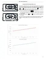
This parameter is used to set the central heating minimum user set
point.
To enter the parameters menu, follow the previously described
procedure (
see paragraph
5.2 ‘Accessing the parameters menu’
-
steps 1-5).
6.
Use ‘
’ and ‘
’ buttons (D.H.W temperature setting)
to
modify the value of the parameter within the prescribed limits
(displayed in Fahrenheit degrees):
68
– 104 (standard appliances)
68 - 86 (reduced for under-floor heating)
7.
Press mode selection button ‘
’ to confirm and to render the
new adjustment operative. The parameter number (P13) will appear
on the display.
8.
To exit from the parameters menu, press simultaneously ‘
’ and
‘
’ buttons.
P
ARAMETER
P14
–
C
ENTRAL HEATING
M
AXIMUM
S
ET POINT
This parameter is used to set the central heating maximum user set
point.
To enter the parameters menu, follow the previously described
procedure (
see paragraph
5.2 ‘Accessing the parameters menu’
-
steps 1-5).
6.
Use ‘
’ and ‘
’ buttons (D.H.W temperature setting)
to
modify the value of the parameter within the prescribed limits
(displayed in Celsius degrees):
104
– 185°F (standard appliances)
104
– 125°F (reduced for under-floor heating)
7.
Press mode selection button ‘
’ to confirm and to render the
new adjustment operative. The parameter number (P14) will appear
on the display.
8.
To exit from the parameters menu, press simultaneously ‘
’ and
‘
’ buttons.
P13
40
P13
30
80
P14
90
P14
Summary of Contents for PNCC-32N
Page 8: ...GENERAL INFORMATION 5 ...
Page 9: ...GENERAL INFORMATION 6 ...
Page 10: ...GENERAL INFORMATION 7 ...
Page 11: ...GENERAL INFORMATION 8 ...
Page 14: ...INSTALLATION INSTRUCTIONS 11 2 2 Dimensions ...
Page 15: ...INSTALLATION INSTRUCTIONS 12 2 3 Internal parts of the boiler ...
Page 16: ...INSTALLATION INSTRUCTIONS 13 2 5 Water circuit ...
Page 17: ...INSTALLATION INSTRUCTIONS 14 2 5 Circulation pump head flow graph ...
Page 35: ...INSTALLATION INSTRUCTIONS 32 ...
Page 41: ...INSTALLATION INSTRUCTIONS 38 36 ...
Page 43: ...INSTALLATION INSTRUCTIONS 40 ...
Page 45: ...INSTALLATION INSTRUCTIONS 42 ...
Page 76: ...MAINTENANCE INSTRUCTIONS 73 6 10 Exploded Drawings ...
Page 77: ...MAINTENANCE INSTRUCTIONS 74 ...
Page 78: ...MAINTENANCE INSTRUCTIONS 75 ...
Page 79: ...MAINTENANCE INSTRUCTIONS 76 ...


