4.
In the
Offset from Reset Setpoint Selection
screen,
press
Up
or
Down
to select the Reset Setpoint Offset
value for the output. Select an OSET value to shift
the (floating) Reset Setpoint (RSP) that the output
references to a (floating) offset reset setpoint (RSP
+OSET).
- A positive offset value (OSET = +
n
) raises
the target reset setpoint referenced by the
output.
- A negative offset value (OSET = -
n
) lowers
the target reset setpoint referenced by the
output.
OSET is typically used to set up sequential off-
set reset setpoint values and stage multiple
Relay Outputs. For example, four boilers can
be staged with 0, 2, 4, and 6 (°F) OSET values
to stage the four boilers ON according to load
increases. (You can also enable bAL to load bal-
ance the boiler runtimes. See
the Load Balancing feature.) See Table 3 for the
range of usable OSET values for the outputs
with RSP in your control system.
Press
Next
to save your value and go to the
next screen.
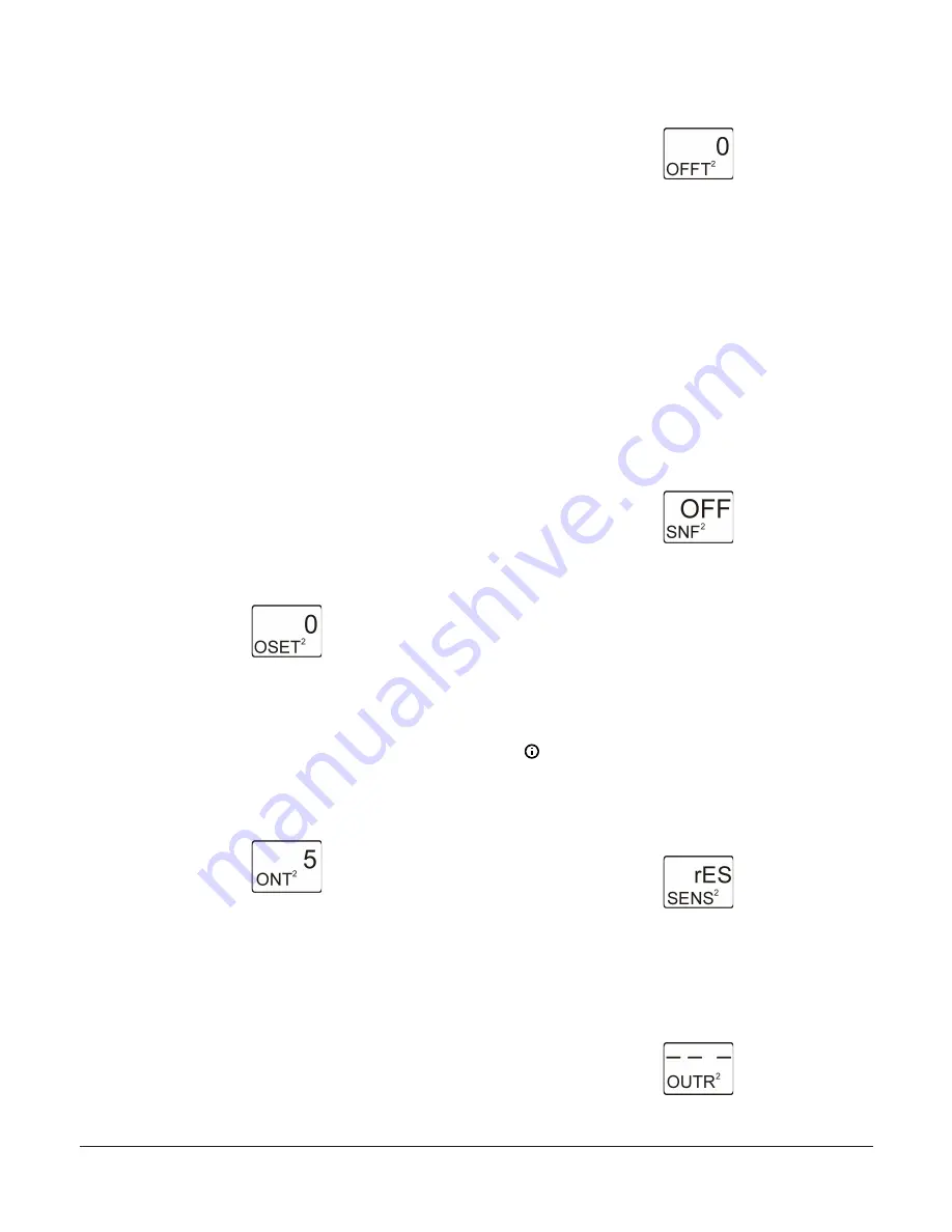
The following figure shows 0 (°F) offset selected
for Output 2.
Figure 38: Offset from Reset Setpoint Selection screen
5.
In the
Minimum Relay ON Time Selection
screen,
press
Up
or
Down
to select the minimum time that
the output relay remains On after reaching the
Relay ON value. Minimum ON Time range is 0 to 300
seconds. Press
Next
to save your selection and go to
the next screen.
The following figure shows 5 seconds selected
for the minimum ON-Time for Output 2.
Figure 39: Minimum Relay ON Time Selection screen
6.
In the
Minimum Relay OFF Time Selection
screen,
press
Up
or
Down
to select the minimum time that
the output relay remains Off after reaching the Relay
OFF value. Minimum OFF Time range is 0 to 300
seconds. Press
Next
to save your selection and go to
the next screen.
The following figure shows 0 seconds selected
for the minimum OFF-Time for Output 2.
Figure 40: Minimum Relay OFF Time Selection screen
7.
In the
Sensor Failure Mode Selection
screen, press
Up
or
Down
to select the output’s mode of operation
if the referenced sensor or sensor wiring fails. The
output operates in the selected mode until the
failure is remedied.Sensor Failure mode selections
for Relay Outputs include:
-
ON
—output relay remains On during sensor
failure.
-
OFF
—output relay remains Off during sensor
failure.
Press
Next
to save your selection and go to the
next screen.
The following figure shows OFF sensor failure
mode selected for Output 2.
Figure 41: Sensor Failure Mode Selection screen
8.
To change the output’s sensor, press
Up
or
Down
in
the
Edit Sensor
screen to select the sensor that the
output references. After you select a different sensor,
press
Next
to go to the required output selection
screen and repeat the output setup procedure for
the new Sensor Type values.
If you do not need to change the output’s sen-
sor, press
Next
in the
Edit Sensor
screen to
save the current sensor selection, complete the
output setup, and return to the Output Setup
Start screen.
Note:
If you change the sensor that an output
references, the default setup parameters and
values for the output change, and you must set
up the output again.
Figure 42: Edit Sensor screen
9.
The Relay Output with Reset Setpoint is now set up
in the UI. In the
Relay Output Setup Start
screen,
press
M
to scroll through the remaining Setup Start
screens and continue setting up your control system,
or press
Up
and
Down
simultaneously to return to
the System 450 Main screens.
Figure 43: Relay Output Setup Start screen
System 450 Series Reset Control Modules with Real-Time Clock and Relay Output Installation Guide
15


