Figure 10: Sn-2 Sensor Type Selection screen
Note:
If your control system does not use
three sensors, simply press
Next
while the two
dashes are flashing in a Sensor Type Selection
screen to save no Sensor Type and go to the
next screen.
4.
In the
Sn-3 Sensor Type Selection
screen, press
Up
or
Down
to select the desired Sensor Type (°F, °C, rH,
or --). Press
Next
to save your selection and go to the
Temperature Offset Setup screen for Sn-1.
The following figure shows Sn-3 set to rH.
Figure 11: Sn-3 Sensor Type Selection screen
5.
Press
Up
or
Down
to select a temperature offset
value. Press
Next
and either:
- go to the next
Temperature Offset Selection
screen (if there are additional temperature
sensors in your control system) and repeat
this step for each temperature sensor.
- return to the
Sensor Setup Start
screen.
The following figure shows 0 as the selected
temperature display offset value for Sensor 2.
Figure 12: Temperature Display Offset Selection
screen
Select a temperature offset for each tempera-
ture (only) sensor in your control system. The
selected offset value is added to the sensed
temperature value to calculate the displayed
temperature value (sensed °F + OFFS = dis-
played °F). The Temperature Display Offset
value is typically 0 or a very low value.
Sensor Type
°F
enables an offset of +/- 5°F in 1
degree increments. Sensor Type
°C
enables an
offset of +/- 2.5°C in 0.5 degree increments.
6.
Press
M
to scroll through the remaining Setup Start
screens and continue setting up your control system,
or press
Up
and
Down
simultaneously to return to
the System 450 Main screens. The hardwire sensors
are setup in the UI.
Figure 13: Sensor Setup Start screen
Setting up the System 450 Reset
Setpoint
The System 450 Reset Control Modules feature
temperature and humidity setpoint reset capability based
on a Master temperature sensor (Sn-1) and a control loop
sensor (Sn-2).
You easily can set up a custom calculated (floating)
Reset Setpoint (RSP) that can be referenced by any of
the outputs in your control system. All control system
outputs that are set up to reference the Reset Setpoint
sensor (rES) use the same RSP setup parameters and RSP
to control output. During normal operation the current
RSP is displayed in one of the Main screens.
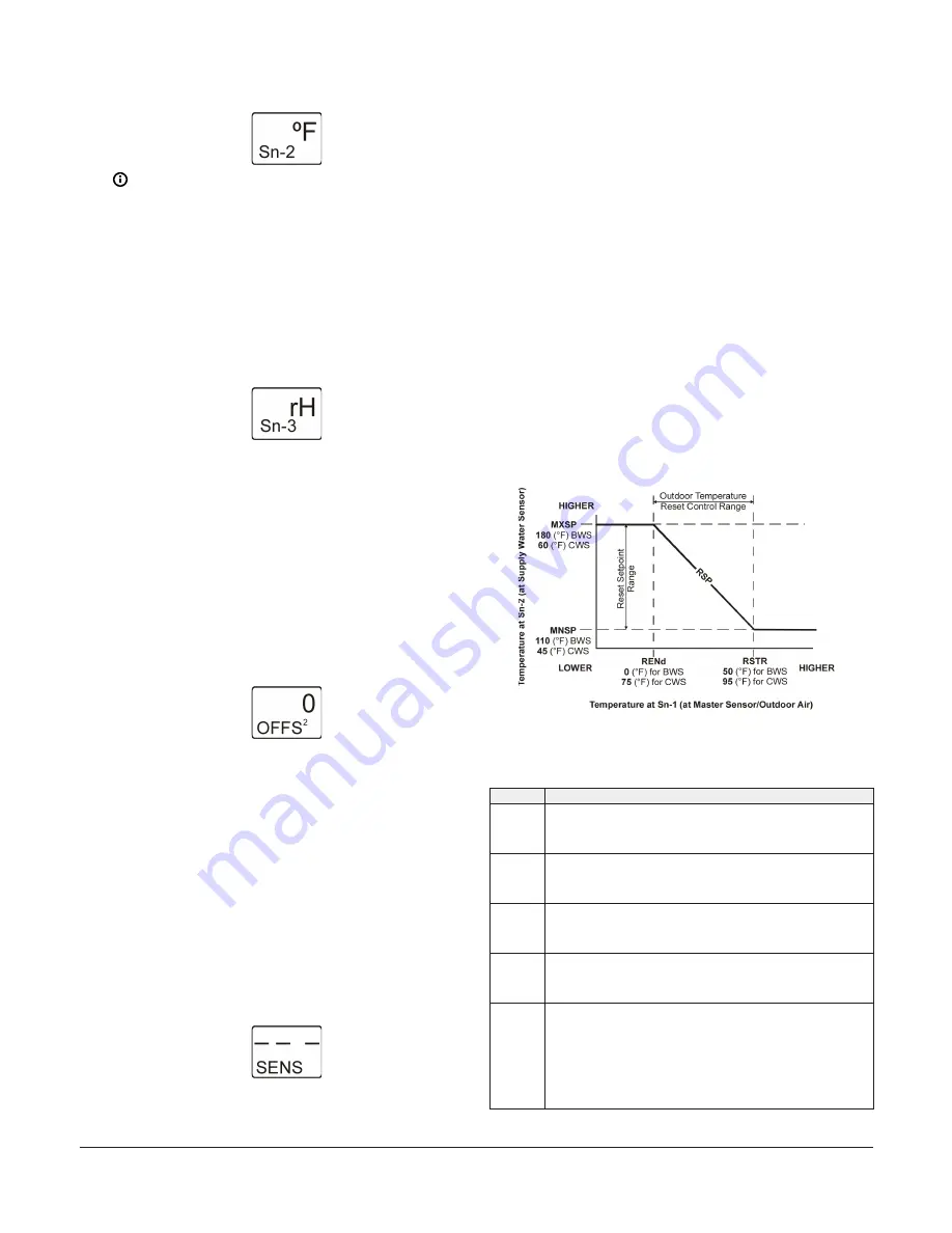
The following figure and table illustrate the relationships
between the setup parameters that define the calculated
RSP.
Figure 14: Example Reset Setpoint Applications for
Boiler Water Supply and Chiller Water Supply showing
the relationships between the Reset Setpoint Setup
parameters
Table 4: Example Reset Setpoint Applications for Boiler
Water Supply and Chiller Water Supply details
Item
Description
MNSP
Minimum Reset Setpoint
(110 [°F] BWS Temperature)
(45 [°F] CWS Temperature)
MXSP
Maximum Reset Setpoint
(180 [°F] BWS Temperature)
(60 [°F] CWS Temperature)
RSTR
Reset Range Start Temperature
(50 [°F] Outdoor Air for BWS)
(95 [°F] Outdoor Air for CWS)
RENd
Reset Range End Temperature
(0 [°F] Outdoor Air for BWS)
(75 [°F] Outdoor Air for CWS)
RSP
Calculated (Floating) Reset Setpoint
From 0 to 50°F outdoor air, the Boiler Water Supply (BWS) setpoint is reset
between 180 and 110°F. Above 50°F outdoor air, the BWS setpoint is 110°F.
Below 0°F outdoor air, the BWS is 180°F.
From 75 to 95°F outdoor air, the Chiller Water Supply (CWS) setpoint is
reset between 60 and 45°F. Above 95°F outdoor air, the CWS setpoint is
45°F. Below 75°F outdoor air, the CWS is 60°F.
System 450 Series Reset Control Modules with Real-Time Clock and Relay Output Installation Guide
9


