5.
In the
Output Signal Strength at Setpoint
Selection
screen, press
Up
or
Down
to select the
output’s %Output Signal Strength at Setpoint value.
Select the strength of the signal that the output
generates when the sensed condition is at the
Setpoint value. Signal strength range is 0 to 100 (%).
Press
Next
to save your selection and go to the next
screen.
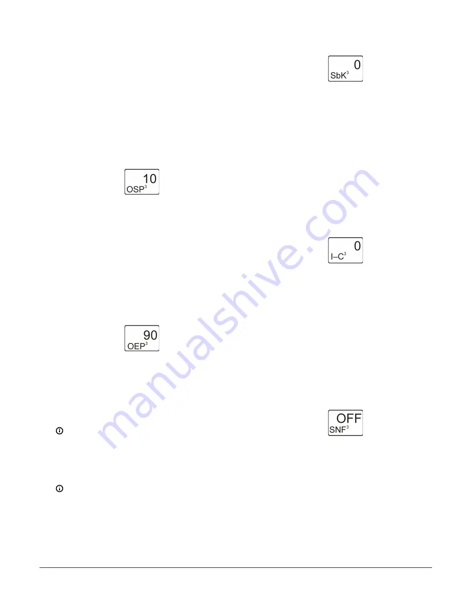
The following figure shows Analog Output 3
is set up to generate 10% of the total signal
strength when the input is at the Setpoint value
(= 1 V or 5.6 mA).
Figure 49: Output Signal Strength at Setpoint Selection
screen
6.
In the
Output Signal Strength at End Point
Selection
screen, press
Up
or
Down
to select the
output’s %Output Signal Strength at End Point value.
Select the strength of the signal that the output
generates when the sensed condition is at the End
Point value. Signal strength range is 0 to 100 (%).
Press
Next
to save your selection and go to the next
screen.
The following figure shows Output 3 is set up to
generate 90% of the total signal strength when
the input is at the End Point value (= 9 V or 18.4
mA).
Figure 50: Output Signal Strength at End Point Selection
screen
7.
In the
Unoccupied Setback Selection
screen, press
Up
or
Down
to select the Unoccupied Setback value.
The selected setback (SbK) value (temperature
or humidity) is added to the SP value (SP+SbK)
and EP value (EP+SbK) to calculate a setback
proportional band that the output references during
the unoccupied times set up in the Occupied/
Unoccupied Schedule Setup screens. Press
Next
to
save the selected value and go to the next screen.
Note:
To use the Setback feature in your
control system, you must also set up the (real)
time and day of week, and a weekly occupied/
unoccupied schedule. See
for more information and
setup procedures.
Note:
Setback set point temperature does
not exceed MXSP or go lower than MNSP. In
reset, MNSP and MXSP are limits to set point
excursion.
The following figure shows 0 selected for the
Unoccupied Setback value for Output 3.
Figure 51: Unoccupied Setback Selection screen
8.
In the
Integration Constant Selection
screen, press
Up
or
Down
to select the Integration Constant for
the output. An integration constant allows you to set
up Proportional plus Integral (P+I) control for this
analog output. When properly set up, P+I control can
drive the load closer to Setpoint than proportional-
only control. Press
Next
to save your selection and
go to the next screen.
Initially, you should select the I-C value of 0
(zero) for no integration constant. Refer to the
System 450 Series Modular Controls Technical Bul-
letin (LIT-12011459)
for more information on pro-
portional plus integral control and setting an
integration constant in the System 450 UI.
The following figure shows an Integration Con-
stant of 0 (zero) selected for Output 3.
Figure 52: Integration Constant Selection screen
9.
In the
Sensor Failure Mode Selection
screen, press
Up
or
Down
to select the Sensor Failure Mode for
the output. You can select the output’s mode of
operation in the event of a sensor or sensor wiring
failure. The output operates in the selected mode
until the failure is fixed. Press
Next
to save your
selection and go to the next screen.
Sensor Failure Mode selections for Analog Out-
puts include:
-
ON
—output goes to the OEP value.
-
OFF
—output goes to the OSP value.
The following figure shows the OFF Sensor Fail-
ure Mode selected for Output 3.
Figure 53: Sensor Failure Mode Selection screen
10. If you do not need to change the output’s sensor,
press
Next
in the
Edit Sensor
screen to save the
current sensor selection, complete the output setup,
and return to the Output Setup Start screen.
To change the output’s sensor, press
Up
or
Down
in the
Edit Sensor
screen to select the
sensor that the output references. After you
select a different sensor, press
Next
to go to
the required output selection screen and repeat
the output setup procedure for the new Sensor
Type values.
System 450 Series Reset Control Modules with Real-Time Clock and Relay Output Installation Guide
18


