9.
In the
Load Balancing Selection
screen, press
Up
or
Down
to enable (ON) or disable (OFF) the Load
Balancing feature for your Reset Control system.
When the System 450 Load Balancing feature is
enabled (ON), the control system uses the relay ON
time of each Relay Output that references the RSP
sensor and balances the total ON times of these
Relay Outputs by cycling ON the Relay Output with
the lowest total ON-time first, and the second lowest
ON-time second, and so on. Press
Next
to save
your selection and return to the Reset Setpoint Start
screen.
Note:
The Load Balancing feature is not
available for analog outputs.
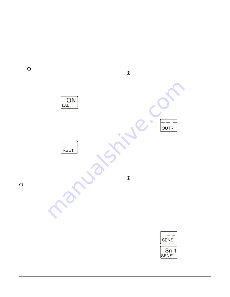
The following figure shows Load Balancing
feature is enabled (ON).
Figure 23: Load Balancing Selection screen
10. In the
Reset Setpoint Setup Start
screen, press
M
to
scroll through the remaining Setup Start screens and
continue setting up your control system, or press
Up
and
Down
simultaneously to return to the System
450 Main screens. The Reset Setpoint is now set up in
the UI.
Figure 24: Reset Setpoint Setup Start screen
Setting up System 450 Outputs
After you build and connect power to your control system
module assembly, the output numbers and output types
for your control system are automatically assigned in the
UI.
Note:
You must set up the system sensors for your
control system before you can set up the outputs.
1.
Access the System 450 setup screens. (See
.) The
Sensor Setup
Start
screen appears.
2.
At the
Sensor Setup Start
screen, press
M
repeatedly to scroll through and select the desired
Output Setup Start
screen. The Output Setup Start
screen indicates the output number and the output
type for the selected output.
To set up Standard System 450 outputs without Reset
Setpoint, see the following sections:
•
Setting up a Standard Relay Output
•
Setting up a standard Analog Output
To set up System 450 outputs with Reset Setpoint, see the
following sections:
•
Setting up a Relay Output with Reset Setpoint
•
Setting up an Analog Output with Reset Setpoint
Setting up a Standard Relay Output
A standard relay output provides On/Off control for your
application based on a fixed setpoint sensor (Sn-1, Sn-2,
or Sn-3).
1.
In the
Relay Output Setup Start
screen, press
Next
to go to the Sensor Selection screen. The
output number and output type (relay or analog) are
automatically assigned when you connect power to
the module assembly. See the Standard Relay Output
Setup Screens row in the setup screens flow chart in
.
Note:
All Setup Start screens are view-only;
selections cannot be made in Setup Start
screens.
The following figure shows the
Relay Output
Setup Start
screen for Output 4. The remaining
screens in this table show the parameter
values selected for controlling the boiler water
circulation pump connected to Relay Output 4
in Figure 3.
Figure 25: Relay Output Setup Start screen
2.
In the Sensor Selection screen, press
Up
or
Down
to
select the Sensor (Sn-1, Sn-2, or Sn-3) that the output
references. The sensor you select here determines
the output control type (standard or reset control),
and output’s setup parameters and value ranges.
Press
Next
to save your sensor selection and go
to the next screen. If a sensor is not selected, the
remaining output setup screens do not appear. If a
sensor is already selected for the output, the Sensor
Selection screen does not appear here and the next
screen in the setup sequence appears instead.
Note:
To set up a Standard Relay Output, you
must select Sn-1, Sn-2, or Sn-3 in this screen,
and the selected sensor must already be set
up in the System 450 UI. See
for information and procedures on
setting up sensors.
The following figure shows the initial Relay
Output 4 Sensor Selection screen with no
sensor selected, followed by the same screen
with the (Master) Sensor 1 selected for Relay
Output 4.
Figure 26: Sensor Selection screens
System 450 Series Reset Control Modules with Real-Time Clock and Relay Output Installation Guide
12


