Setting up System 450 Sensors
You must set up the sensors (inputs) for your control system before you can set up any of the outputs. See
. The following table provides information about System 450 compatible sensors for Reset
Control Modules.
provides a System 450 UI screen flowchart example.
Table 3: System 450 Reset Control sensor types, setup values, and product codes
Sensor
type
Unit of
measuremen
t value
Range of
usable
values
Resolution
increment
s value
Minimum
differential
or
proportiona
l band
Effective
sensing
range
Range of
usable Pb/
dIFF and
SbK values
for RSP
Range of
usable
OSET
values for
RSP
Sensor
product
type
number
°F
°F
-40 to 250 1
1
-46 to 255
-30 to 30
-30 to 30
A99B-xxx
°C
°C
-40 to 121 0.5
0.5
-43 to 124
-17 to 17
-17 to 17
A99B-xxx
rH
% Humidity
10 to 95
1
2
1 to 100
-20 to 20
-30 to 30
HE-67Sx-x
1.
In the
Sensor Setup Start
screen, press
Next
to go
to the first Sensor Type Selection screen (Sn-1) and
begin setting up the sensors in your control system.
Press
M
(repeatedly) to scroll through the remaining
Setup Start screens.
The
Sensor Setup Start
screen is the first
screen displayed when you access the System
450 setup screens. From the Sensor Setup Start
screen you can navigate to all of the remaining
Setup Start screens in your control system. See
.
The following figure shows the
Sensor Setup
Start
screen with flashing dashes.
Figure 8: Sensor Setup Start screen
Note:
You must set up the sensors for your
control system, including the reset setpoint
sensor (rES) (if required for your application)
before you can set up the control system
outputs. All Setup Start screens are view-
only; selections cannot be made in Setup Start
screens.
2.
In the
Sn-1 Sensor Type Selection
screen, press
Up
or
Down
to select a Sensor Type (°F, °C, or --).
Press
Next
to save your selection and go to the Sn-2
Sensor Type Selection screen.
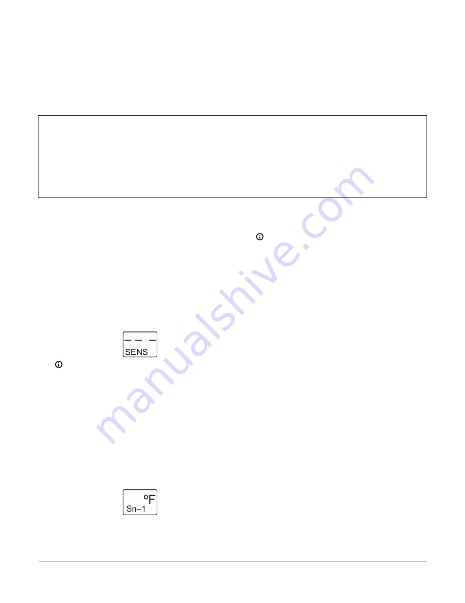
The following figure shows Sn-1 set to Sensor
Type °F.
Figure 9: Sn-1 Sensor Type Selection screen
The Sensor Type you select for an input sensor
automatically determines the setup parameters
and values for each output that is set up to ref-
erence that sensor. See Table 3 for information
about System 450 sensors/transducers, sensor
types, setup values, and product code numbers.
Note:
- System 450 Reset Control Modules are
designed for use with temperature (°C or
°F) and humidity (rH) Sensors Types only.
Pressure Sensor Types are not available
in the reset control module UI. You also
can select no Sensor Type (- -) when your
control systems uses less than three
sensors.
- In System 450 reset control systems,
Sensor 1 (Sn-1) is the Master sensor and
must always be a temperature sensor.
Sn-2 must be the control loop sensor.
The Sn-1 Master sensor is typically (but
not always) an outdoor air temperature
sensor. Sensor 2 (Sn-2) and Sensor 3
(Sn-3) can be temperature or humidity,
depending on your application. The
Reset Setpoint sensor (rES) cannot be set
up for your control system until both the
Sn-1 and Sn-2 are set up in the UI.
- For an output to operate properly,
the selected Sensor Type must match
the sensor model wired to the control
module, and the correct sensors must
be wired to the correct control module
input terminals.
3.
In the
Sn-2 Sensor Type Selection
screen, press
Up
or
Down
to select the desired Sensor Type (°F, °C, rH,
or --). Press
Next
to save your selection and go to the
Sn-3 Sensor Type Selection screen.
The following figure shows Sn-2 set to °F.
System 450 Series Reset Control Modules with Real-Time Clock and Relay Output Installation Guide
8


