9.
If you do not need to change the output’s sensor,
press
Next
in the Edit Sensor screen to save the
current sensor selection, complete the output setup,
and return to the Output Setup Start screen.
To change the output’s sensor, press
Up
or
Down
in the Edit Sensor screen to select the
sensor that the output references. After you
select a different sensor, press
Next
to go to
the required output selection screen and repeat
the output setup procedure for the new Sensor
Type values.
Note:
If you change the sensor that an output
references, the default setup parameters and
values for the output change, and you must set
up the output again.
Figure 33: Edit Sensor screen
10. The Standard Relay Output is now set up in the UI.
Press
M
to scroll through the remaining Setup Start
screens and continue setting up your control system,
or press
Up
and
Down
simultaneously to return to
the System 450 Main screens.
Figure 34: Relay Output Setup Start screen
Setting up a Relay Output with Reset
Setpoint
A relay output with reset setpoint provides On/Off control
to your application based on the Reset Setpoint sensor
(rES) that you set up for your control system.
1.
In the
Relay Output Setup Start
screen, press
Next
to go to the Sensor Selection screen. The
output number and output type (relay or analog)
are automatically assigned when you connect power
to the module assembly. See the Relay Output
with Reset Setpoint Setup Screens row in the setup
.
Note:
All Setup Start screens are view-only;
selections cannot be made in Setup Start
screens.
The following figure shows the
Relay Output
Setup Start
screen for Output 2. The remaining
figures in this procedure show screens with the
parameter values selected for Relay Output 2
to control the temperature of Boiler 1 in Figure
Figure 35: Relay Output Setup Start screen
2.
In the
Sensor Selection
screen, press
Up
or
Down
to
select the Reset Setpoint Sensor (rES) for the output
to reference. The sensor selected here determines
the output control type (standard or reset control),
and the output’s setup parameters and value ranges.
Press
Next
to save your sensor selection and go to
next screen. If a sensor is not selected, the remaining
output setup screens do not appear. If a sensor is
already selected for the output, the Sensor Selection
screen does not appear here, the next screen in the
setup sequence appears instead.
Note:
To set up a Relay Output with Reset
Setpoint, you must select rES in this screen. rES
cannot be selected until the Reset Setpoint is
set up in the System 450 UI. See
procedures on setting up the RSP and rES.
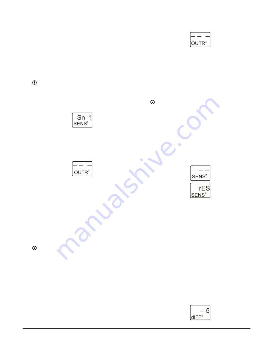
The following figure shows the initial
Relay
Output 2 Sensor Selection
screen with no
sensor selected, followed by the same screen
with the Reset Setpoint sensor (rES) selected for
Relay Output 2.
Figure 36: Relay Output 2 Sensor Selection screens
3.
In the
Reset Differential Selection
screen, press
Up
or
Down
to select the Reset Differential value for
the output. Select a dIFF value to establish the fixed
differential between the floating Relay-OFF setpoint
(RSP) and the floating Relay-ON setpoint (RSP+dIFF).
See Table 3 for the (fixed) minimum differential and
the range of usable dIFF values for outputs with RSP
in your control system.
- A positive differential (dIFF = +
n
) turns the
relay ON when temperature or humidity
increases; typically cooling.
- A negative differential (dIFF = -
n
) turns the
relay ON when temperature or humidity
decreases; typically heating.
Press
Next
to save your selection and go to the
next screen.
The following figure shows -5 differential
selected for Output 2.
Figure 37: Reset Differential Selection screen
System 450 Series Reset Control Modules with Real-Time Clock and Relay Output Installation Guide
14


