Peco Pro 12 DFS 52621201 Operator'S Manual Download Page 28

28

    condition. Repair or replace any missing or damaged 

4. Perform lubrication.

3. Make sure all shields are in place and in good 

5. Listen for abnormal sounds, which might indicate 
    loose parts, damaged bearings, or other damage. 
    Correct any deficiency before continuing operation.

    shields.

6. With the engine off, engage the blower assembly. 

    cracks or tears.

7. Check for wear or deterioration of the upper or lower 

    Check the belt tension and inspect the pulley belt for 

After Each Use:

1. Clean all debris from machine especially from the 

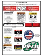
    decals. Replace any missing or illegible decals.

    PECO parts.

    been torn or worn through, replace with genuine 

    hoses. If there are any portions of the hose that have 

    container, underneath the belt shields, and safety 

2. Inspect the unit for worn or damaged components. 
    Repair or replace before the next use. Any 
    replacement component installed during repair shall 
    include the component’s current safety decal specified 

3. Check belt for proper tension.

    by the manufacturers to be affixed to the component.

DOCUMENT THE FOLLOWING INFORMATION FOR FUTURE REFERENCE

Unit Model Number:_______________________________________________

Unit Serial Number:________________________________________________

Unit  Engine  Size:__________________________________________________

Date of purchase:________/________/_________

Address: _________________________________ State:_______ Zip:_______

Dealer/Distributor Name:__________________________________________

Phone Number: ____________________________________________________

100 AIRPORT ROAD

(800) 438-5823  OR  (828) 684-1234   FAX: (828) 684-0858

EMAIL: [email protected]

ARDEN, NORTH CAROLINA 28704

WEBSITE: www.lawnvac.com
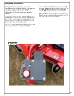
 Lubrication

Gearbox:
  1. Every 20 hours of use: Check oil levels in gearbox.
  2. First 60 hours of use: Change oil.
  3. Every 100 hours of use: Change oil.

  NOTE: 

Oil in gearbox should cover the gears. If not, 

      drain the gearbox and fill using an 80W-90 gear oil. 

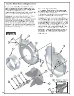
      contain a greaseable zirc fitting. Newer models 

      recommend replacing with a measured 5.5 oz. to fill 

  NOTE:

 Use only white lithium based grease for 

SECTION V - PARTS & SERVICE

Collection system owners should record the name and 
telephone number of their Service Center. Your Service 
Center will be happy to supply replacement parts, 
accessories, and do any service or repairs to your 
collection system. If for any reason your Service Center 
is unable to service your collection system or supply 
replacement parts, contact Country Clipper and include 
the following information on the chart below. 

      The gearbox ships with 6.0 oz. of oil, but we

  NOTE: 

The following is for older PTO models that

      contain maintenance-free bearings and are without

.

      a greasable fitting.

      lubrication of the shaft on the blower assembly.

 Parts And Service Information

Blower Assembly:

  1. On initial use: Grease the fitting on the blower shaft.

      the gearbox. 

DO NOT OVERFILL!

  2. Every 25 hours of use: Re-grease the grease fitting.


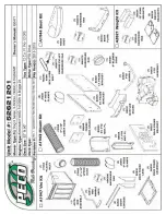
Summary of Contents for Pro 12 DFS 52621201

Page 1: ...Y OPERATION MAINTENANCE MANUAL PART 1 REV 2 06 2018 Q047 PTO GRASS COLLECTION SYSTEM MODEL 52621201 2013 2015 MODEL YEAR OPERATOR S MANUAL P P P PECO PECO PECO PECO PECO PECO P P P P P P P P PECO PECO...

Page 2: ...reign object 12 Wear ear protection if the noise level is offensive 10 It is recommended that the container be kept only half full when negotiating any slopes Start mowing on slopes Introduction 5 Des...

Page 3: ...the vacuum collector ONLY AFTER STOPPING THE MOWER S ENGINE AND WAITING FOR ALL MOVING PARTS TO COME TO A COMPLETE STOP Set the parking brake Always remove the ignition key before beginning maintenanc...

Page 4: ...ge for parts or labor if the ALL DEFECTIVE PARTS MUST BE RETURNED TO PECO FOR INSPECTION TO ways not approved by New PECO Inc paid for by the purchaser Neither New PECO Inc nor any company affiliated...

Page 5: ...llection system is designed for turf maintenance where there is a need to collect the grass clippings as the mower cuts the turf It is also used for picking up leaves and in pre season and post season...

Page 6: ...r equivalent During installation opposite bearing inner race must be supported or bearing damage may occur Refer to Figure C Upon pressing the engine pulley to the clutch replace the completed assembl...

Page 7: ...Figure B Exhaust pipe must be cut off 1 5 from original Left and Right Frame Bracket Installation Secure the left frame bracket P B0826 and right frame bracket P B0825 to the rear frame of the mower...

Page 8: ...ar Frame Bracket Installation Secure the rear frame bracket P B0827 to the left and right frame bracket using 2 3 8 16 x 1 HHCS P K1191 and 2 3 8 16 nylon flange locknuts P K2038 PER BRACKET Refer to...

Page 9: ...1 2 13 x 1 1 4 HHCS P K1232 and 1 1 2 13 nylon flange locknut P K2012 Refer to Figures A and B for mounting holes locations specific to your series X Series Mounting Locations X Diablo Diablo DiabloM...

Page 10: ...ch the handle grip P J0522 to the PTO handle Refer to Figure A and B NOTE The PTO Handle can be adjusted after performing installation to achieve proper belt adjustment To adjust the handle remove 3 1...

Page 11: ...drive belt turn the adjustment bolt clockwise Figure E until there is 1 of deflection with 10 11 lbs of pressure at the center of the belt between the engine pulley and the gear box pulley Once the co...

Page 12: ...ted If the belt is too tight or becomes too loose remove the hair pin clip P K0099 from the belt tension rod P K0326 and pull the L end of the rod out of it s hole in the cam assembly The tension rod...

Page 13: ...Series mounting locations Main Frame Assembly Installation Lift the main frame assembly P A0995 into position as shown in Figure A Secure the main frame assembly to the main frame legs using 4 3 8 16...

Page 14: ...s shown in Figure D using 1 5 16 24 hex nut P K1444 and 1 5 16 lock washer P K0043 Attach the other end of the latch rod to the lift handle as shown in Figure E Attach on end of the spring P J0176 to...

Page 15: ...le away from the unit and lift upward The door of the container should open and the box should pivot clockwise towards the ground Aluminum Grass Container Installation Dump Mechanism Adjustment The li...

Page 16: ...16 ALUMINUM GRASS CONTAINER EXPLODED VIEW A0614 K1442 V1 131 6...

Page 17: ...ags Figure A shows an exhaust diverter P J0251 and exhaust clamp kit P X1046 installed on the Kawasaki FX850 Any engine that exhaust to the right side or the rear will require an exhaust diverter Slid...

Page 18: ...er attaching the boot plate to the boot lift the grass deflector and hang the boot plate on the discharge chute of the mower deck The boot plate is slotted for positioning once attached to the mower d...

Page 19: ...ng pin Proceed to slide the opposite end of the 6 hose onto the outlet of the blower assembly See Figure A for details Make sure both ends of the hose are clearly attached to the inlet and the blower...

Page 20: ...mpeller blade to ensure that the blade is clear of contact on all sides of the blower housing 2 Spray break free lubricant into the surrounding areas of the taper lock bushing 9 and repeat Tip 1 Impel...

Page 21: ...8 16 nylon flange lock nuts P K2012 PER Bracket Insert the u bolts from the bottom so that the locknuts are on top of the weight bracket NOTE It is recommended that a support such as a floor Jack be u...

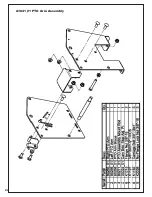
Page 22: ...22 A1841_01 PTO Arm Assembly...

Page 23: ...23 A1941_01 PTO Base Assembly Exploded Parts View...

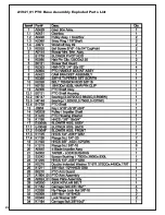
Page 24: ...24 A1941_01 PTO Base Assembly Exploded Parts List...

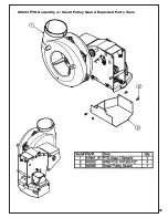
Page 25: ...25 A0623 PTO Assembly w Small Pulley Guard Exploded Parts View...

Page 26: ...26...

Page 27: ...OTE If you do not hold the handle away from the mower as you pull the handle downward the latch will not lock and the container can unexpectedly release the contents collected objects such as wire or...

Page 28: ..._____________________ State _______ Zip _______ Dealer Distributor Name __________________________________________ Phone Number ____________________________________________________ 100 AIRPORT ROAD 80...

Page 29: ...R1070 PECO Logo Part R1083 Engage Disengage Part R1069 Warning Turn Off Blower Part R4008 Caution Rotating Blades R2008 R2007 Part R1057 Red Reflector Label TO DUMP GRASS PUSH HANDLE OUT AND LIFT R105...

Page 30: ...30...

Page 31: ...31 NOTES...

Page 32: ...10 WALDEN DRIVE ARDEN NORTH CAROLINA 28704 800 438 5823 OR 828 684 1234 FAX 828 684 0858 EMAIL peco lawnvac com WEBSITE www lawnvac com P P P PECO PECO PECO PECO PECO PECO P P P P P P P P PECO PECO R...

Reviews: