Peco Pro 12 DFS 52621201 Operator'S Manual Download Page 27

27

     deck.

* Remember that horsepower requirements will vary with 

D. While seated in the operator’s seat, rotate the 

* Wet grass and leaves will decrease effectiveness and 

   the grass blade length at any given time.)

   will increase horsepower requirements.

* Watch your speed- Normal conditions will allow a 

     engagement handle of the collection system away 
     from the mower. Continue to rotate the handle until it 

     engaged, you can proceed to operate the control 
     levers of the mower.

NOTE:

 If the collection system does not appear to be 

collecting the grass clippings, disengage the deck
and blower, then, engage the parking brake and turn the 
mower off.  

To obtain the maximum effectiveness from your 
collection system the tips listed below should be 
followed:

   speed of up to approximately 5 mph, but thick, heavy 

C. With the mower at high idle speed, engage the mower 

* Mow with sharp blades- A sharp blade cuts cleaner.

   damp conditions will require reduced ground speed.

   more than 2” of grass length with each mowing. 

     stops in an over center position. With the blower 

* Mow twice, at different height settings, (high, then low), 
   if grass is extra tall.

* Mow at higher cutting heights- Remove and mulch no 

   (Experts recommend not cutting off more than 1/3 of 

   grass, moisture content, amount of leaves, whether the 
   terrain is flat or hilly, etc.

   the mowing conditions such as type and height of turf 

  General Safety


SECTION III

OPERATING 

INSTRUCTIONS

Only qualified people familiar with this operator’s manual 
and the mower’s operator’s manual should operate this 
machine.

 Operation And Tips On Mowing

A. Perform BEFORE EACH USE the maintenance list 
in MAINTENANCE.

B. Start mower.

 Disengagement Of The Blower

NOTE:

 If you do not hold the handle away from the 

mower as you pull the handle downward, the latch will 
not lock and the container can unexpectedly release the 
contents collected.

    objects, such as wire or steel strapping bands, are 

     will swing upward and the container will rotate 


SECTION IV

     operating position. With the handle in the ‘away’ 

MAINTENANCE

     handle towards the mower.

     collection position.

WARNING: 

The blower will continue to spin. DO NOT 

TOUCH the blower, pulleys, or the belt until the tractor is 
turned off. DO NOT adjust the belt tension until the 
mower is turned off. Refer to the belt tension and 
adjustment section of this manual. 

NOTE:

 Press the tab, located behind the operator’s left 

side, downward to feel if the collection system is full. If 
the container is full there will be resistance when 
depressing the tab.

C. Disengage the blower.

     away, move the handle upward. The container door 

 Maintenance Checklist

Unloading The Collection System

B. Disengage the mower deck.

D. Verify that the dump area is clear.
E. Push the dump handle, on the left of the operator, 

     downward. The container will release its contents.
F. Once the contents of the container have fallen out, the 

     away from the unit. While holding the handle pushed 

     position, pull the handle downward until it stops. 

     This motion will allow the latch to lock back into 

A. Stop the forward movement of the mower.

A. To disengage the blower, rotate the engagement 

     Move the handle towards the center of the mower. 

     container is ready to move back into its normal 

NOTE: REMOVE PTO ASSEMBLY BEFORE 

RAISING DECK FOR MAINTENANCE.

Before each use:

1. Check blades and spindles to be sure that no foreign 

2. Inspect blades for wear. Replace if necessary. If it is 
    necessary to sharpen the blades, remove the blades 
    from the spindles before sharpening. DO NOT 
    sharpen blades while still attached to the mower.

    wrapped around them.

Summary of Contents for Pro 12 DFS 52621201

Page 1: ...Y OPERATION MAINTENANCE MANUAL PART 1 REV 2 06 2018 Q047 PTO GRASS COLLECTION SYSTEM MODEL 52621201 2013 2015 MODEL YEAR OPERATOR S MANUAL P P P PECO PECO PECO PECO PECO PECO P P P P P P P P PECO PECO...

Page 2: ...reign object 12 Wear ear protection if the noise level is offensive 10 It is recommended that the container be kept only half full when negotiating any slopes Start mowing on slopes Introduction 5 Des...

Page 3: ...the vacuum collector ONLY AFTER STOPPING THE MOWER S ENGINE AND WAITING FOR ALL MOVING PARTS TO COME TO A COMPLETE STOP Set the parking brake Always remove the ignition key before beginning maintenanc...

Page 4: ...ge for parts or labor if the ALL DEFECTIVE PARTS MUST BE RETURNED TO PECO FOR INSPECTION TO ways not approved by New PECO Inc paid for by the purchaser Neither New PECO Inc nor any company affiliated...

Page 5: ...llection system is designed for turf maintenance where there is a need to collect the grass clippings as the mower cuts the turf It is also used for picking up leaves and in pre season and post season...

Page 6: ...r equivalent During installation opposite bearing inner race must be supported or bearing damage may occur Refer to Figure C Upon pressing the engine pulley to the clutch replace the completed assembl...

Page 7: ...Figure B Exhaust pipe must be cut off 1 5 from original Left and Right Frame Bracket Installation Secure the left frame bracket P B0826 and right frame bracket P B0825 to the rear frame of the mower...

Page 8: ...ar Frame Bracket Installation Secure the rear frame bracket P B0827 to the left and right frame bracket using 2 3 8 16 x 1 HHCS P K1191 and 2 3 8 16 nylon flange locknuts P K2038 PER BRACKET Refer to...

Page 9: ...1 2 13 x 1 1 4 HHCS P K1232 and 1 1 2 13 nylon flange locknut P K2012 Refer to Figures A and B for mounting holes locations specific to your series X Series Mounting Locations X Diablo Diablo DiabloM...

Page 10: ...ch the handle grip P J0522 to the PTO handle Refer to Figure A and B NOTE The PTO Handle can be adjusted after performing installation to achieve proper belt adjustment To adjust the handle remove 3 1...

Page 11: ...drive belt turn the adjustment bolt clockwise Figure E until there is 1 of deflection with 10 11 lbs of pressure at the center of the belt between the engine pulley and the gear box pulley Once the co...

Page 12: ...ted If the belt is too tight or becomes too loose remove the hair pin clip P K0099 from the belt tension rod P K0326 and pull the L end of the rod out of it s hole in the cam assembly The tension rod...

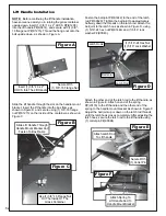
Page 13: ...Series mounting locations Main Frame Assembly Installation Lift the main frame assembly P A0995 into position as shown in Figure A Secure the main frame assembly to the main frame legs using 4 3 8 16...

Page 14: ...s shown in Figure D using 1 5 16 24 hex nut P K1444 and 1 5 16 lock washer P K0043 Attach the other end of the latch rod to the lift handle as shown in Figure E Attach on end of the spring P J0176 to...

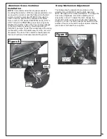
Page 15: ...le away from the unit and lift upward The door of the container should open and the box should pivot clockwise towards the ground Aluminum Grass Container Installation Dump Mechanism Adjustment The li...

Page 16: ...16 ALUMINUM GRASS CONTAINER EXPLODED VIEW A0614 K1442 V1 131 6...

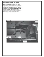
Page 17: ...ags Figure A shows an exhaust diverter P J0251 and exhaust clamp kit P X1046 installed on the Kawasaki FX850 Any engine that exhaust to the right side or the rear will require an exhaust diverter Slid...

Page 18: ...er attaching the boot plate to the boot lift the grass deflector and hang the boot plate on the discharge chute of the mower deck The boot plate is slotted for positioning once attached to the mower d...

Page 19: ...ng pin Proceed to slide the opposite end of the 6 hose onto the outlet of the blower assembly See Figure A for details Make sure both ends of the hose are clearly attached to the inlet and the blower...

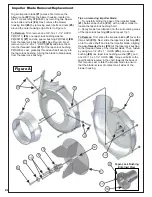
Page 20: ...mpeller blade to ensure that the blade is clear of contact on all sides of the blower housing 2 Spray break free lubricant into the surrounding areas of the taper lock bushing 9 and repeat Tip 1 Impel...

Page 21: ...8 16 nylon flange lock nuts P K2012 PER Bracket Insert the u bolts from the bottom so that the locknuts are on top of the weight bracket NOTE It is recommended that a support such as a floor Jack be u...

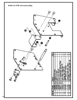
Page 22: ...22 A1841_01 PTO Arm Assembly...

Page 23: ...23 A1941_01 PTO Base Assembly Exploded Parts View...

Page 24: ...24 A1941_01 PTO Base Assembly Exploded Parts List...

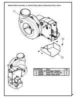
Page 25: ...25 A0623 PTO Assembly w Small Pulley Guard Exploded Parts View...

Page 26: ...26...

Page 27: ...OTE If you do not hold the handle away from the mower as you pull the handle downward the latch will not lock and the container can unexpectedly release the contents collected objects such as wire or...

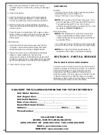
Page 28: ..._____________________ State _______ Zip _______ Dealer Distributor Name __________________________________________ Phone Number ____________________________________________________ 100 AIRPORT ROAD 80...

Page 29: ...R1070 PECO Logo Part R1083 Engage Disengage Part R1069 Warning Turn Off Blower Part R4008 Caution Rotating Blades R2008 R2007 Part R1057 Red Reflector Label TO DUMP GRASS PUSH HANDLE OUT AND LIFT R105...

Page 30: ...30...

Page 31: ...31 NOTES...

Page 32: ...10 WALDEN DRIVE ARDEN NORTH CAROLINA 28704 800 438 5823 OR 828 684 1234 FAX 828 684 0858 EMAIL peco lawnvac com WEBSITE www lawnvac com P P P PECO PECO PECO PECO PECO PECO P P P P P P P P PECO PECO R...

Reviews: