


18
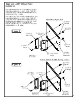
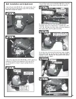
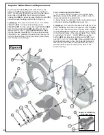
Position the boot plate P#(B0832) onto the top of the
aluminum boot P#(E0025) as shown in Figure A. Secure
the boot plate to the boot using (3) 3/8”-16 x 1” carriage
bolts P#(K1182) and (3) 3/8”-16 nylon flange locknuts
P#(K2038). Insert the bolts from the inside of the boot so
that the locks nuts are on top of the boot plate. This will
prevent grass clipping from collecting on the bolt
threads. Leave the hardware slightly loose until the boot
kit installation is complete.
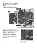
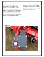
Boot Kit Installation
The boot kit is designed to work on the 52” and 60”
decks. After attaching the boot plate to the boot, lift the
grass deflector and hang the boot plate on the discharge
chute of the mower deck. The boot plate is slotted for
positioning once attached to the mower deck. Slide the
boot forwards or backwards until you eliminate any gaps
between the discharge chute and boot. You want the
boot to fit as closely as possible to the mower deck to
prevent grass blow-out. Once the boot has been
positioned properly, tighten the boot kit hardware. Refer
to Figures A, B & C for reference.
Side Profile of the
Boot Plate. This Notch
Will Hang The Boot From
The Mower Deck
Hang Boot Plate
On Mower Deck Edge
(3) 3/8”-16 x 1”
Carriage Bolts
(3) 3/8”-16 Locknuts
Boot Plate
Grass
Deflector
B
O
O
T
P
L
A
T
E
Figure B
Figure C
Figure A
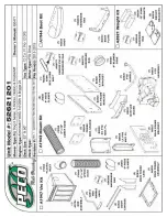
Summary of Contents for Pro 12 DFS 52621201
Page 16: ...16 ALUMINUM GRASS CONTAINER EXPLODED VIEW A0614 K1442 V1 131 6...
Page 22: ...22 A1841_01 PTO Arm Assembly...
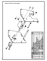
Page 23: ...23 A1941_01 PTO Base Assembly Exploded Parts View...
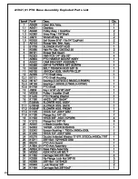
Page 24: ...24 A1941_01 PTO Base Assembly Exploded Parts List...
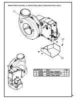
Page 25: ...25 A0623 PTO Assembly w Small Pulley Guard Exploded Parts View...
Page 26: ...26...
Page 30: ...30...
Page 31: ...31 NOTES...


