


11
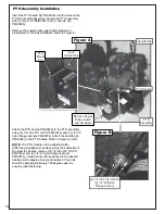
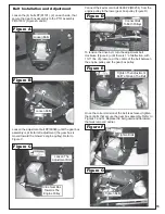
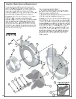
Loosen the (4) bolts P#(K1191), (2) on each side, that
secure the gear box assembly to the PTO assembly
P#(A1803) (Figures A and B).
Belt Installation and Adjustment
Loosen the adjustment bolt P#(K0348) until the gear box
assembly is at its far left adjustment (the gear box is
moved toward the mower’s engine pulley). Refer to
Figure C.
Connect the kevlar cord belt A59K P#(M0254) from the
engine pulley to the lower gear box pulley (Figure D).
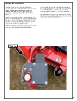
To tension the drive belt, turn the adjustment bolt
clockwise (Figure E) until there is 1” of deflection, with
10-11 lbs. of pressure, at the center of the belt between
the engine pulley and the gear box pulley.
Once the correct tension of the belt is achieved, tighten
the (4) bolts that secure the gear box assembly. Refer to
Figures F and G. Replace the belt guard and hardware
that was removed earlier.
Loosen Bolts
Loosen Bolts
Loosen The
Adjustment Bolt
Slide Gear Box
Towards The
Engine Pulley
Connect Belt
To Both Pulleys
Tighten Bolts
Tighten Bolts
Tighten The Adjustment
Bolt To Tension The Belt
Figure D
Figure E
Figure F
Figure G
Figure A
Figure B
Figure C
Summary of Contents for Pro 12 DFS 52621201
Page 16: ...16 ALUMINUM GRASS CONTAINER EXPLODED VIEW A0614 K1442 V1 131 6...
Page 22: ...22 A1841_01 PTO Arm Assembly...
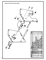
Page 23: ...23 A1941_01 PTO Base Assembly Exploded Parts View...
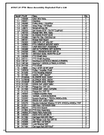
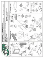
Page 24: ...24 A1941_01 PTO Base Assembly Exploded Parts List...
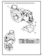
Page 25: ...25 A0623 PTO Assembly w Small Pulley Guard Exploded Parts View...
Page 26: ...26...
Page 30: ...30...
Page 31: ...31 NOTES...


