


20
3
2
4
5
1
3
5
6
7
8
9
10
12
13
11
14
9
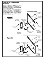
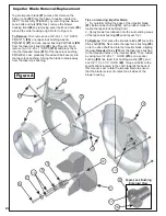
Taper-Lock Bushing
Enlarged View
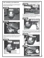
Tips on removing impeller blade;
1 - Try carefully hitting the base of the impeller blade
(#1)
, between each vein
(#12)
, with a rubber mallet to
loosen the taper-lock bushing hold.
To Replace:
First, place the impeller blade
(#1)
over the
drive shaft
(#13)
. Next, slide the taper-lock bushing
(#9)
on to the drive shaft and into the impeller blade, aligning
the
non-threaded
holes
(#14)
of the taper-lock bushing
to the threaded holes of the impeller blade. Then, fasten
by using two 1/4”-20 x 1” HHCS
(#10)
, one spacer
bushing
(#8)
one taper lock bushing washer
(#7)
, and
one 3/8”-16 x 1-1/2” HHCS
(#6)
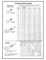
. Torque all bolts to the
specifications located in the chart towards the back of
this manual. Last, rotate the impeller blade to ensure
that the blade is clear of contact on all sides of the
blower housing.
2 - Spray break-free lubricant into the surrounding areas
of the taper-lock bushing
(#9)
and repeat Tip 1.
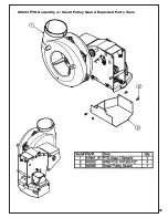
Impeller Blade Removal/Replacement
To gain impeller blade
(#1)
access, first remove the
blower cone
(#2)
from the blower housing, located on
the PTO assembly P#(A0623), by removing two blower
cone bolts and nuts
(#3)
. Next, remove the blower
housing front
(#4)
by removing seven bolts and nuts
(#5)
around the outer housing edge
.
Refer to Figure A.
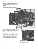
To Remove:
First, remove one 3/8”-16 x 1-1/2” HHCS
P#(K1211)
(#6)
, one taper-lock bushing washer
P#(K0278)
(#7)
and one spacer bushing P#(S3242)
(#8)
from the taper-lock bushing
(#9)
. See Figure A. Next,
remove two 1/4”-20 x 1” HHCS
(#10)
and place them
into the threaded holes
(#11)
of the taper-lock bushing
P#(S4302). Last, gradually thread each bolt evenly into
the taper-lock bushing, forcing the blade to break-away
from the taper-lock bushing.
Figure A
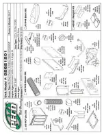
Summary of Contents for Pro 12 DFS 52621201
Page 16: ...16 ALUMINUM GRASS CONTAINER EXPLODED VIEW A0614 K1442 V1 131 6...
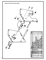
Page 22: ...22 A1841_01 PTO Arm Assembly...
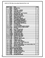
Page 23: ...23 A1941_01 PTO Base Assembly Exploded Parts View...
Page 24: ...24 A1941_01 PTO Base Assembly Exploded Parts List...
Page 25: ...25 A0623 PTO Assembly w Small Pulley Guard Exploded Parts View...
Page 26: ...26...
Page 30: ...30...
Page 31: ...31 NOTES...


