


12
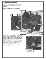
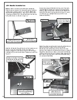
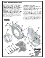
Thread (1) 5/16”-18 jam nut P#(K0120) onto each end of
(2) 5/16”-18 x 2-1/2” HHCS P#(K0125). Now partially
thread the bolts into each of the two tabs located on the
blower housing. Place blower cone P#(E6009) so the
two tabs line up with the bolts then tighten completely.
See Figure B.
Blower Cone Installation
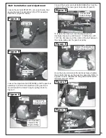
Cam Assembly Adjustment
The cam assembly P#(A0422), which controls the
blower belt tension, comes from the factory pre-adjusted.
If the belt is too tight or becomes too loose, remove the
hair pin clip P#(K0099) from the belt tension rod
P#(K0326) and pull the “L” end of the rod out of it’s hole
in the cam assembly. The tension rod may then be
screwed out to tighten the belt or screwed in to loosen
the belt. Replace the “L” end into the top hole in the cam
and replace the hair pin clip. Adjust the cam stop bolt
P#(K1159) to allow the cam to rotate slightly over center
when the blower is disengaged (Figure A).
Cam Assembly
Tension Rod
Cam Stop
Blower
Cone Tabs
Blower
Cone
Hair Pin Clip
(2) 5/16”-18 x 2-1/2”
All Thread HHCS
(2) 5/16” Jam Nuts
Figure A
Figure B
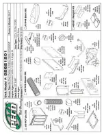
Summary of Contents for Pro 12 DFS 52621201
Page 16: ...16 ALUMINUM GRASS CONTAINER EXPLODED VIEW A0614 K1442 V1 131 6...
Page 22: ...22 A1841_01 PTO Arm Assembly...
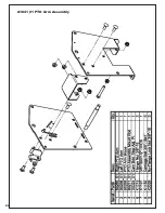
Page 23: ...23 A1941_01 PTO Base Assembly Exploded Parts View...
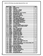
Page 24: ...24 A1941_01 PTO Base Assembly Exploded Parts List...
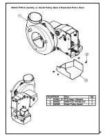
Page 25: ...25 A0623 PTO Assembly w Small Pulley Guard Exploded Parts View...
Page 26: ...26...
Page 30: ...30...
Page 31: ...31 NOTES...


