


19
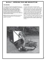
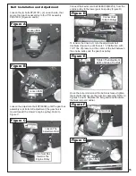
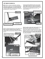
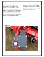
Upper Hose Installation
Length Of Hose Adjustment
ends of the 6” upper hose (Figure A). Then slide one
Slide a pre-assembled hose clamp P#(J1000) onto both
The hoses must be cut to fit your machine. Do not cut
the hoses until you have tried to fit them on your
machine. Remember that the hoses have to be long
enough to adjust for the blower assembly’s movement
as well as allow for enough clamping surface between
the inlet, blower assembly, and the deck boot.
end of the 6” hose onto the plastic inlet P#(V1054) on
the right side of the aluminum box assembly. Make sure
there is about a two-inch overlap between the hose end
and plastic inlet. Secure the hose ring with the locking
pin. Proceed to slide the opposite end of the 6” hose
onto the outlet of the blower assembly. See (Figure A)
for details. Make sure both ends of the hose are clearly
attached to the inlet and the blower assembly inlet.
Tighten the hose clamps.
Take the unattached end of the lower hose and slide it
clamp to secure the hose to the boot (Figure A). Tip:
Slide a pre-assembled hose clamp P#(J1000) over both
ends of the lower hose. Then proceed to slide the lower
hose onto the blower cone. Tighten the hose clamp. The
assembly should look like Figure A.
Lower Hose To Blower Cone
Installation
Lower Hose To Boot Installation
over the circular end of the boot. Use the lower hose
Before securing clamp rotate hose counter-clockwise
boot to mower deck.
(away from yourself) approximately 1” to aid in retaining
Inlet
Lower
Hose
Boot
Hose
Clamps
Blower
Cone
Blower
Outlet
Upper
Hose
Figure A
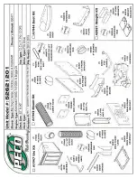
Summary of Contents for Pro 12 DFS 52621201
Page 16: ...16 ALUMINUM GRASS CONTAINER EXPLODED VIEW A0614 K1442 V1 131 6...
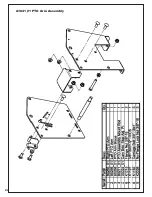
Page 22: ...22 A1841_01 PTO Arm Assembly...
Page 23: ...23 A1941_01 PTO Base Assembly Exploded Parts View...
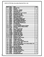
Page 24: ...24 A1941_01 PTO Base Assembly Exploded Parts List...
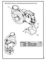
Page 25: ...25 A0623 PTO Assembly w Small Pulley Guard Exploded Parts View...
Page 26: ...26...
Page 30: ...30...
Page 31: ...31 NOTES...


