


Status 14.07.09
We reserve the right to make
changes favouring technical
progress.
Operating Instructions
thermos 200 / 300 DC
with automatic control unit
®
WÄRMERÜCKGEWINNUNG
© Paul Wärmerückgewinnung GmbH • August-Horch-Straße 7 • 08141 Reinsdorf • Deutschland
Tel: +49(0)375-303505-0 • Fax: +49(0)375-303505-55 • E-Mail: [email protected] • Internet: www.paul-lueftung.de
4
The control unit of the MVHR must be equipped for controlling a frost protection heater. The frost
protection heater has to be activated and parameterised via the control unit in the system setup menu (see
User Guidance of Automatic Control Unit, Section 2.1).
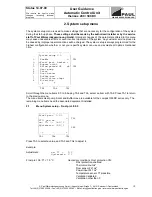
2.5
Electric duct heater
Electric or ISO duct heaters can be used as back-up heaters for the supply air. They are controlled via the
MVHR control system specifically equipped for this purpose. The duct heaters include the prescribed
safety appliances. A duct temperature sensor is used to limit the air temperature to 50°C, because higher
temperatures would cause dust particles to smoulder (undesired smells). The duct heaters are switched on
or off as a function of room temperature, duct temperature and temperature setpoint.
If the room temperature falls below the setpoint, the duct heater will start operating, and will stop when the
setpoint is exceeded. The room temperature is recorded by a temperature sensor in the programmer or by
an external room temperature sensor.
The setpoint is selected and the heater activated via the control unit (see User Guidance of Automatic
Control Unit, Section 2.4). A lower night-time temperature can be programmed. Connections shall be made
according to Appendix 2.1, Appendix 3.2, and Appendix 4.4.a for electric back-up duct heaters with ohmic
heating element, and to Appendix 4.4.b for ISO back-up duct heaters with PTC heating element.
Note:
The control unit can operate only
one
heating circuit (electric duct heater, hot water duct heater, or
heating circuit)!
2.6
Hot water duct heater
A hot water duct heater can be used to heat the supply air. It is controlled via the MVHR control system
specifically equipped for this purpose. A duct temperature sensor is used to limit the air temperature to 50
°C, because higher temperatures would cause dust particles to smoulder. The duct heater is switched on
or off (hot water circulating pump) as a function of room temperature, duct temperature and temperature
setpoint.
If the room temperature falls below the setpoint, the duct heater will start operating, and will stop when the
setpoint is exceeded. The room temperature is recorded by a temperature sensor in the programmer or by
an external room temperature sensor.
The setpoint is selected and the heater activated via the control unit (see User Guidance of Automatic
Control Unit, Section 2.4). A lower night-time temperature can be programmed. Connections shall comply
with Appendix 2.1, Appendix 3.2, and Appendix 4.2.
Note:
The control unit can operate only
one
heating circuit (hot water duct heater, electric duct heater, or
heating circuit)!
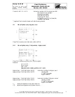
2.7
Control for 1 heating circuit
(e. g. circulating pump for panel heaters or radiators)
The control unit of the MVHR must be specifically equipped for this purpose. A temperature sensor is used
to limit e.g. the flow temperature to 50°C (parameterisable). The heating circuit is switched on or off as a
function of room temperature, flow temperature and temperature setpoint.
If the room temperature falls below the setpoint, the heating circuit (pump) will start operating, and will stop
when the setpoint is exceeded. The room temperature is recorded by a temperature sensor in the
programmer or by an external room temperature sensor.
The setpoint is selected and the heating circuit activated via the control unit (see User Guidance of
Automatic Control Unit). A lower night-time temperature can be programmed. The connection shall be
made according to Appendix 4.2 as described for the hot water heating register.
Note:
The control unit can operate only
one
heating circuit (heating circuit, hot water duct heater, or
electric duct heater)!
2.8
External boost switch
One or several boost switches can be connected with the programmer. Pressing the boost switch means
maximum fan power for 15 minutes. The connection shall be made according to Appendix 4.1.
Summary of Contents for thermos 300 DC
Page 2: ......
Page 46: ......
Page 47: ......
Page 48: ......
Page 52: ......
Page 53: ......
Page 54: ......
Page 55: ......
Page 56: ......
Page 57: ......
Page 58: ......
Page 59: ......
Page 60: ......
Page 61: ......
Page 62: ......
Page 63: ......
Page 64: ......
Page 65: ......
Page 66: ......


