Paul thermos 300 DC Operating Instructions Manual Download Page 6

Status 14.07.09 

 
We reserve the right to make 
changes favouring technical 
progress.


Operating Instructions 

thermos 200 / 300 DC 

with automatic control unit


®

WÄRMERÜCKGEWINNUNG


© Paul Wärmerückgewinnung GmbH • August-Horch-Straße 7 • 08141 Reinsdorf • Deutschland  

Tel: +49(0)375-303505-0 • Fax: +49(0)375-303505-55  • E-Mail: [email protected] • Internet: www.paul-lueftung.de 


2

1.6 Filters 


The MVHR unit includes two Z-shape G4 filters (dust filters). They are made of a cotton/polyester fabric in 
a frame. A high-quality pollen filter (rated F 8) can be used as an option in the supply air. 

 
1.7 Application 

limits 


The MVHR is designed for the use in residential and office buildings, in schools and retirement homes 
(with certain limits in industrial application) at air temperatures of up to +40°C and normal air humidity. 
Explosive and aggressive gases as well as solvents attacking the materials in the system are not allowed. 
The unit has to be installed in a frost-free room. A ground to air heat exchanger would be advantageous 
for pre-heating the intake air (in winter). If a ground heat exchanger is not feasible, a frost protection pre-
heater or a ground to brine to air frost protection must be installed upstream of the unit. 
 

1.8 Flammability 


The housing of the unit is chiefly made of PP foam (normally flammable). Other components are hardly or 
normally flammable (heat exchanger, ventilation fans); the filter with the cardboard frame (flammable) can 
be considered a subordinate component. So the unit complies with the building regulations. 


2. Options and accessories


2.1 Basic 

version 


The compact mechanical ventilation heat recovery (MVHR) unit comprises the heat recovery unit itself, the 
central control unit with power pack, and the programmer with display and room temperature sensor.  
The control system with the programmer controls enables the user to freely select the minimum, normal 
and maximum ventilation steps without limitation in time. But the ventilation steps can also be stored in 8 
independent programs, which can be assigned to the different days of the week. This allows for fully 
automatic operation with different fan power. The ventilation steps can be changed in 1% increments for 
adapting the MVHR unit to the duct system. The supply and extract air flows are balanced via a coefficient 
of correction allowing different fan speeds to be adjusted for the same ventilation step. The detailed 
procedure is described in section 2.5 of the User Guidance of the Automatic Control Unit. 


The summer bypass valve is series equipment. It is actuated via temperature sensors and the control unit.  
It is used for automatically bypassing the heat exchanger in summer. The internal motorised bypass valve 
is controlled as a function of intake and extract air temperatures.  
The bypass is open e.g. 

t

EXT

 > 23°C and t

INT

 < t

EXT

 (cooling function) 


t

EXT

 < 19°C und t

INT

 > t

EXT

 (heating function is possible too) 

The temperature sensors are installed in the unit at the manufacturer’s site. 
The bypass must be enabled (activated) and parameterised (see User Guidance of Automatic Control Unit, 
Section 2.2). 
To ensure the bypass valve functions properly, it is necessary to remove the supply air bypass shut-off 
insert from the unit. For better tightness, the shut-off insert should be put back in place for the winter 
period. 


The MVHR unit can be switched off manually at the programmer without disconnecting it from the power 
mains. This specific switching-off function limits the power input in standby condition to less than 2 W. 


Furthermore, this automatically provides the necessary frost protection of any downstream hot water back-
up heater. 


Summary of Contents for thermos 300 DC

Page 1: ...uctions P lease keep next to the MVHR unit P lease keep next to the MVHR unit W RMER CKGEWINNUNG with automatic control unit Components suitable for Passive House Dr Wolfgang Feist Status 07 09 Paul W...

Page 2: ......

Page 3: ...sensor Additional programmer MVHR Installation Installation of the mechanical ventilation heat recovery MVHR unit air duct connections Power supply electric control Connection and maintenance of the c...

Page 4: ...endix 1 1 Terminal assignment of control unit Appendix 1 2 Internal terminal diagram thermos 200 300 DC Appendix 2 1 External connection diagram thermos 200 300 DC Appendix 2 2 Legend of external conn...

Page 5: ...ustomer who shall also provide the control unit s connection with the power supply 1 2 Housing heat and sound insulation The fan and heat exchanger box subassemblies are releasably connected by means...

Page 6: ...ck and the programmer with display and room temperature sensor The control system with the programmer controls enables the user to freely select the minimum normal and maximum ventilation steps withou...

Page 7: ...ogue flow sensors to be integrated in straight tubes of the same diameter see Appendix 3 3 and Appendix 4 5 When setting the parameters it is possible to store a flow disbalance The constant flow cont...

Page 8: ...d via the MVHR control system specifically equipped for this purpose A duct temperature sensor is used to limit the air temperature to 50 C because higher temperatures would cause dust particles to sm...

Page 9: ...icone to create airtight connections After each cleaning operation every 2 years re assemble the fan box and the heat exchanger box press tightly and lock them using the blue assembly caps Leave enoug...

Page 10: ...ped at their low point refer to Figure 2 Schematic sketch for condensate discharge line with MVHR 90 thermos Figure 1 Caution U bend traps can dry out Always refill water when starting up the unit hea...

Page 11: ...the duct install a throttle valve or a foam flow restrictor Balance the air flows at the MVHR unit if required Equal supply and extract flows vary the fan power to balance the flows the extract flow m...

Page 12: ...the front 10 Re connect the MVHR unit with the power supply re energise General inspection of the MVHR unit 1 Contamination 2 Electrical safety 3 Leaktightness of condensate connection The supply and...

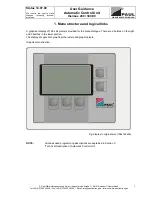
Page 13: ...Mail info paul lueftung de Internet www paul lueftung de 1 1 Menu structure and logical links A graphical display of 128 x 64 pixels is provided for the menu dialogue There are 2 buttons on the right...

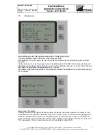
Page 14: ...or code is indicated refer to error code table Pressing the button TA2 illuminates the display screen for 1 minute Operating a boost switch connected to the programmer causes the ventilation to run at...

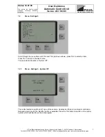
Page 15: ...nd TA5 up down arrows press TA2 to select an item Press TA1 to return to the basic menu The pre selected function is System Off 1 2 1 Menu Settings 0 System Off The control system is switched off none...

Page 16: ...controlled Electric duct heater ohmic heating element is controlled ISO duct heater PTC heating element is controlled Static heating elements pump is controlled Night reduction Reduction of room temp...

Page 17: ...0 days Press TA3 and TA4 to increase or reduce the number of days for the interval After reset the day counter starts a countdown for the remaining service time After the interval has lapsed the basic...

Page 18: ...days but to assign Program 2 to the weekend The programs can be edited by the user in the menu Programs 5 0 Use TA5 to scroll through the weekdays and press TA3 TA4 to select the desired program numb...

Page 19: ...rmal Normal ventilation max Maximum ventilation A system is generally designed and dimensioned for normal ventilation So the minimum or zero steps mean that there is less air exchange than assumed in...

Page 20: ...rams will not run properly Press TA5 to scroll through the time and date until all values are set then press Save to acknowledge and store the values Save will appear on the screen when all settings h...

Page 21: ...turn to the Menu Settings T intake Intake air temperature at the inlet of the unit T supply Supply air temperature at the outlet of the unit T heat Supply air temperature at the outlet of the duct hea...

Page 22: ...s always programmed for the highest configuration whether or not your specific system can use and evaluate all options mentioned here System setup 9 0 9 Enable TA1 0 Frost prot heater 1 Bypass su wi 2...

Page 23: ...pass su wi Bypass su wi 9 1 0 TA1 0 Temperatures 1 Servomotor ok TA2 TA5 TA4 TA3 Press TA5 to select a menu item and confirm with TA2 2 2 1 Menu System setup Temperatures Bypass su wi Bypass su wi 9 1...

Page 24: ...motor Bypass su wi Setup bypass su wi 9 1 1 0 TA1 min max act Bp1 100 255 100 TA2 NOTE The values are just examples TA5 TA4 TA3 Press TA5 to select a value and TA3 TA4 to adjust it min Closed max Open...

Page 25: ...ure below setpoint and Maximum duct temperature not reached DCTH Off Room temperature exceeds setpoint or Maximum duct temperature reached Example x0 21 0 C Duct heater ON T5 20 5 C H0 0 5 K Duct heat...

Page 26: ...needed in the system SUP EXT for positive fan adjustment e g ebm fans of series campus thermos atmos for negative fan adjustment e g Papst fans of series multi climos are used to adjust the response o...

Page 27: ...will restart automatically after validation with TA5 2 7 Menu System setup Enable 9 9 0 Enable 9 9 0 0 Frost prot heater ON TA1 1 PTC heater OFF 2 Brine ground HX OFF 3 Bypass 1 OFF ok TA2 4 Bypass 2...

Page 28: ...display shows x The button TA5 gives access to service menu 1 3 2 Service menu 1 Frost prot brine GHX valve Service1 FP brine GHX FHL Off T7 x TA1 x1 02 0 H1 01 0 STB FZ1 IFZ1 Brine GHX f Off T2 22 0...

Page 29: ...selected k cooling mode disabled heating is not possible T0 Room temperature X0 Room temperature setpoint H0 Hysteresis f r x0 x0 H0 T5 Duct temperature X5 Max duct temperature H5 hysteresis for x5 x...

Page 30: ...X X 0 30 X X X X X X X 0 45 X X X X X X X 1 00 X X X X X X X 1 15 X X X X X X X 1 30 X X X X X X X 1 45 X X X X X X X 2 00 X X X X X X X 2 15 X X X X X X X 2 30 X X X X X X X 2 45 X X X X X X X 3 00 X...

Page 31: ...X X X X 14 00 X X X X X X 14 15 X X X X X X 14 30 X X X X X X 14 45 X X X X X X 15 00 X X X X X X 15 15 X X X X X X 15 30 X X X X X X 16 00 X X X X X X 16 15 X X X X X X 16 30 X X X X X X 16 45 X X X...

Page 32: ...ngs 1 Settings 2 Settings 3 Settings 4 Unit in standby Enable ON OFF Filter change Temperature setpoints Programs day Unit OFF Air heating 1 0 Filter interval 2 0 Temperatures 3 0 Programs day 4 0 Nig...

Page 33: ...4 0 Unit OFF Tempe ratures 9 1 0 0 HP bypasses 9 3 0 0 Cut off temperature Servo motor 9 1 1 0 Fixing temp window for flap valve Position OFF 9 3 1 0 Define solar pump Position Heat 9 3 2 0 Position C...

Page 34: ...1 0XXXXXXXXX No faults in this group 1XXXXXXXXX FAULT IN ROOM TEMPERATURE SENSOR T0 2XXXXXXXXX FAULT IN INTAKE AIR TEMPERATURE SENSOR T1 3XXXXXXXXX FAULT IN ROOM TEMPERATURE SENSOR T0 FAULT IN INTAKE...

Page 35: ...X No faults in this group X1XXXXXXXX FAULT IN EXTRACT AIR TEMPERATURE SENSOR T4 X2XXXXXXXX FAULT IN BACK UP HEATER DUCT TEMPERATURE SENSOR T5 X3XXXXXXXX FAULT IN EXTRACT AIR TEMPERATURE SENSOR T4 FAUL...

Page 36: ...T FZ4 FAULT IFZ1 FAULT IFZ4 XXXFXXXXXX FAULT FZ1 FAULT FZ4 FAULT IFZ1 FAULT IFZ4 XXXX0XXXXX No faults in this group XXXX1XXXXX FAULT FROST PROTECTION HEATER IS NOT DETECTED XXXX2XXXXX FAULT BACK UP DU...

Page 37: ...tion of the control system it is possible to set up simple as well as complex control configurations covering all PAUL mechanical ventilation control variants The photograph shows a fully equipped con...

Page 38: ...ine pump on PP 8 GND 9 NPN open collector output PP power standby from HCE 10 GND 11 PWM Out fan2 extract air 12 GND 13 PWM Out fan1 supply air 14 GND 15 24P from PP 16 GND 17 24P from PP 18 GND 19 24...

Page 39: ...rotection pre heater additional switch module required Air duct heater additional switch module required Constant flow control Connector pin assignment Plug X3 1 T1 NTC temp sensor for intake air at i...

Page 40: ...echnical Description Automatic Control thermos 200 300 DC Paul W rmer ckgewinnung GmbH August Horch Stra e 7 08141 Reinsdorf Deutschland Tel 49 0 375 303505 0 Fax 49 0 375 303505 55 E Mail info paul l...

Page 41: ...tallation in building system refer to electrical connection instructions Fuses single phase mains 1x16 A external three phase mains 3x16 A external internal mains fuse 2A M internal on PP internal fus...

Page 42: ...ion of the power pack take care to ensure the individual phases are loaded symmetrically Use a 3 core cable for direct load connection to connector 2 of the power module inverted 3 pole plug To select...

Page 43: ...utschland Tel 49 0 375 303505 0 Fax 49 0 375 303505 55 E Mail info paul lueftung de Internet www paul lueftung de 7 4 1 Terminal connection plan for switch module Switch module 2 1 KW 230 V INPUT from...

Page 44: ...cation The programmer can be used to view enter or change any parameters of the mechanical ventilation control unit The programmer offers menu dialogues so all settings are self explaining There are t...

Page 45: ...lve frost protection brine pump T2 Outdoor temperature x2 min temp GHX valve OPEN pump ON x4 max temp GHX valve OPEN pump ON H2 hysteresis for x2 and x4 x4 Menu 9 2 0 Setup GHX valve brine pump Valve...

Page 46: ......

Page 47: ......

Page 48: ......

Page 49: ...is switched on and off by the control unit Sensor equipment for electric back up duct heater Comprising flow indicator thermal cut out and duct temperature sensor for monitoring the electric duct hea...

Page 50: ...ion appropriate length to be laid by customer l Sensor line T5 control unit Copper strand with PVC insulation LiYY 2 0 5mm 5V DC Sensor mit Kabel und Stecker werksseitig vorkonfektioniert nur Sensor w...

Page 51: ...xt to each other or in the same cable duct because this might cause parasitic induction and disturb the sensor elements A minimum distance of 20 cm 8 inches is recommended Install the control unit in...

Page 52: ......

Page 53: ......

Page 54: ......

Page 55: ......

Page 56: ......

Page 57: ......

Page 58: ......

Page 59: ......

Page 60: ......

Page 61: ......

Page 62: ......

Page 63: ......

Page 64: ......

Page 65: ......

Page 66: ......

Page 67: ...n single phase 230V 50Hz three phase 3 x 230V 50 Hz with frost protection and back up duct heater options Central control unit LxWxD mm 340x300x80 or 340x300x140 with frost protection and back up duct...

Page 68: ...ower input below 2 W manual adjustment of ventilation steps off minimum normal maximum programmer can be installed in any place in the house ventilation steps programmable in 1 increments 30 100 of ma...

Page 69: ...e filters in fresh air pipe Suctioning in of outside air also in the soil heat exchanger Quarterly Year I II III IV 200 201 201 201 201 4 Exhaust hood Clean grease filters every 6 8 weeks with hot wat...

Page 70: ...d heat exchanger c at extract air valves d check filter change intervals by inspecting the records of the tenant owner e record any filter change in writing 3 Check intake air ducts for contamination...

Page 71: ...3 Check insulation visual examination a damage b moisture penetration c connection point at MVHR unit d line to valve connection 14 Check fire dampers if any a inspect test report b latch and trigger...

Page 72: ...s Very dirty Fan speed ratio clean extract supply air Supply air Ventilation step Project Data Measurement data Valve No Room description m h m s m h m s mm Extract air Ventilation step Project Data M...

Reviews: