


Status 14.07.09
We reserve the right to make
changes favouring technical
progress.
Operating Instructions
thermos 200 / 300 DC
with automatic control unit
®
WÄRMERÜCKGEWINNUNG
© Paul Wärmerückgewinnung GmbH • August-Horch-Straße 7 • 08141 Reinsdorf • Deutschland
Tel: +49(0)375-303505-0 • Fax: +49(0)375-303505-55 • E-Mail: [email protected] • Internet: www.paul-lueftung.de
7
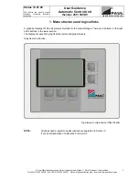
4. Start-up
4.1
Readiness for operation
•
Fill U bend trap with water
•
Bypass shut-off (insert in autumn, winter, spring; remove in summer)
•
Connect the control unit with the power supply, establish the electrical connections of the MVHR unit,
the programmer and the additional components with the control unit according to the circuit diagrams
(Appendix),
observe the instructions (Appendix)
, the MVHR system is ready for operation
•
Select the automatic mode
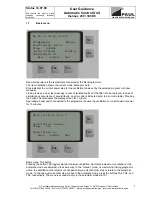
4.2
Air flow settings
Air flow settings are made via fan power adjustments with the bypass shut-off insert in place. (factory
setting: see Technical Data -Characteristics-) Select the appropriate characteristic curve for normal
ventilation (70%) according to the ductwork design (equal pressure loss for all duct runs, e. g. 100 Pa) and
the required total air flow, and adjust the fan power at the programmer. Supply and extract air flows can be
set to different values, e.g.: if a ground to air heat exchanger is used, it may be necessary to increase the
power of the supply air fan via the correction value. (for guidance: see User Guidance for Automatic
Control Unit).
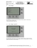
4.3
Commissioning of valves (supply and extract flows)
•
Set the fans to
normal ventilation
at the programmer
•
Balance the air flows at the air valves using a capture hood and an anemometer (see air flow report)
•
Set the ventilation slot at the valve, make sure it is not too narrow – risk of flow noise! Better: Reduce
the fan power or throttle the air flow early in the duct (install a throttle valve or a foam flow restrictor)
•
Balance the air flows at the MVHR unit (if required): Equal supply and extract flows (vary the fan power
to balance the flows), the extract flow may be slightly higher than the supply flow
•
Readjust the valves
•
Record the values in the enclosed “Air flow report”
5. Care and maintenance by owner (user)
(refer to check list A)
5.1 General
User maintenance is limited to the periodical cleaning of filters and supply and extract valves. Never allow
the MVHR system to run without filters. Therefore, always switch off the unit for maintenance. Pollen filters
should be replaced by the user immediately after the pollination period (depending on the pollen the user is
allergic to).
Make a filter check after an operating time of 90 days.
Filter change intervals according to
EN 1946-10 are 3 to 6 months. The filters can be obtained from PAUL; it is not possible to clean the filters
in place in the MVHR unit. The filter mats of the extract valves (e.g. bathroom, kitchen, toilet) shall be
replaced or cleaned (warm water with washing-up liquid) every 2 or 3 months, or at the user’s own
discretion after filter checks.
5.2 Filter
change
Replace the supply and extract air filters in the MVHR unit when the message
[CHANGE FILTER]
appears
on the display of the programmer. The preset filter interval is 90 days. Other intervals can be programmed
at your own discretion (see User Guidance of Automatic Control Unit, Section 1.2.3).
To change filters, remove the two cover panels from the left front of the MVHR unit, the upper panel for the
extract filter and the lower panel for the intake air filter. The foam housing is provided with recessed grips
for easier handling. Each filter insert is masked by a plastic panel with grip band. Remove the panels.
Insert and position the filters correctly according to the prescribed flow direction
(as identified by the
arrow
⇑
)
and the specified insert depth as shown in the associated labels. Then put all cover panels back
in place in reverse order.
Summary of Contents for thermos 300 DC
Page 2: ......
Page 46: ......
Page 47: ......
Page 48: ......
Page 52: ......
Page 53: ......
Page 54: ......
Page 55: ......
Page 56: ......
Page 57: ......
Page 58: ......
Page 59: ......
Page 60: ......
Page 61: ......
Page 62: ......
Page 63: ......
Page 64: ......
Page 65: ......
Page 66: ......


