


Status 14.07.09
We reserve the right to make
changes favouring technical
progress.
Operating Instructions
thermos 200 / 300 DC
with automatic control unit
®
WÄRMERÜCKGEWINNUNG
© Paul Wärmerückgewinnung GmbH • August-Horch-Straße 7 • 08141 Reinsdorf • Deutschland
Tel: +49(0)375-303505-0 • Fax: +49(0)375-303505-55 • E-Mail: [email protected] • Internet: www.paul-lueftung.de
6
3.3
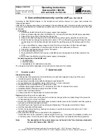
Connection and maintenance of the condensate drain hose G ¾”
Lay the condensate drain hose with continuous
slope (min 5%). Do not reduce its diameter. Make
sure the condensate can drip off freely at the end
with the hose being entirely emptied. If there is
risk of frost, the hose must be heated (tracer can
be delivered). Any rising or horizontal duct
connected to the exhaust air outlet shall be
provided with a condensate trap at its low point.
Also, ground to air heat exchangers need to be
trapped at their low point (refer to Figure 2).
Schematic sketch for condensate
discharge line with MVHR 90-thermos
Figure 1
Caution: U-bend traps can dry out!
Always refill water when:
•
starting up the unit
•
hearing a noise from trap (slurping noise)
•
noticing smells from the sewage system in the building
•
air passes through the trap
•
a dry trap can be recommended and is available for delivery (preventing smells from getting into
the air in case of drying out)
If a low point cannot be avoided in the exhaust ducting between the exhaust air outlet of the unit and the
wall penetration, connect another condensate discharge there, because at low outdoor temperatures the
exhaust air is saturated with water vapour and causes drops to form at the inner walls of the duct. If a
silencer is installed at the exhaust outlet of the MVHR unit, it must form a top bend (
∩
) to be protected
from condensate backflows from the exhaust air duct. The MVHR unit should be installed in a way to
ensure sufficient slope for proper condensate discharge over a longer distance.
Figure 2
Summary of Contents for thermos 300 DC
Page 2: ......
Page 46: ......
Page 47: ......
Page 48: ......
Page 52: ......
Page 53: ......
Page 54: ......
Page 55: ......
Page 56: ......
Page 57: ......
Page 58: ......
Page 59: ......
Page 60: ......
Page 61: ......
Page 62: ......
Page 63: ......
Page 64: ......
Page 65: ......
Page 66: ......


