background image

Using a browser to complete Model 2616RC configuration

37

Model 2616RC T-DAC User Manual 

3 • Configuring the T-DAC for operation
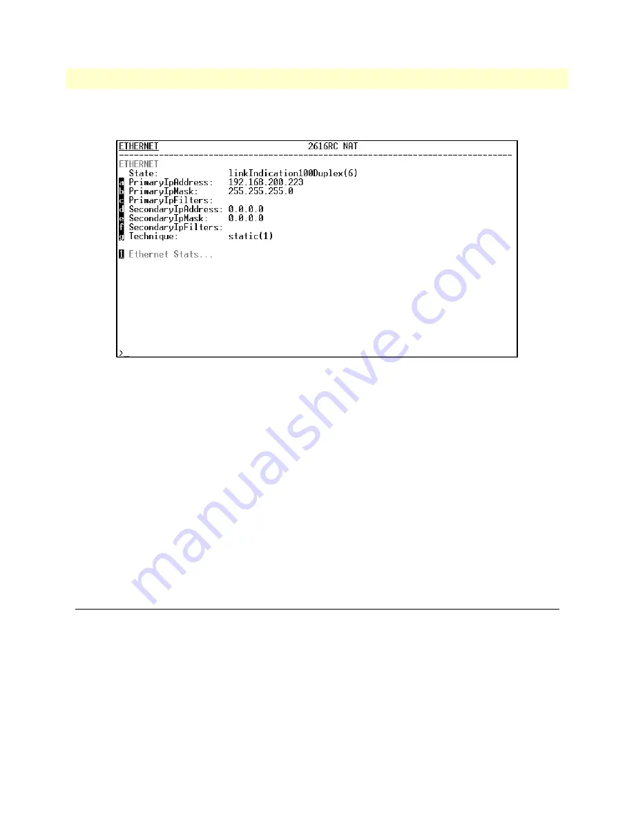
13.

Type 

e

 for Ethernet, then press 

<Enter>

. The 

Ethernet

 configuration window displays (see 

figure 22

).

Figure 23. Ethernet configuration window

14.

Enter 

a

 for 

PrimaryIpAddress

, then press 

<Enter>

.

15.

Type your LAN IP address followed by pressing 

<Enter>

.

16.

Press the left-arrow cursor key on your keyboard to return to the previous screen.

17.

If you do not need to change the PrimaryIpMask from the default of 255.255.255.0, go to step 20. Other-
wise, type 

b

 and type the new LAN Mask in the same manner as when entering a LAN IP address.

18.

Press the left-arrow cursor key until the top level management window displays (see 

figure 22

 on page 36).

19.

Type 

a

 for 

HOME

, then press 

<Enter>

.

20.

Under the 

Current Status

 page, type 

1

 (

store Config(1)

) to save the changes you have just made to 

the configuration. 

This completes the initial configuration of the Model 2616RC. The next steps in configuration will be done 
using your Web browser connected via Ethernet to the 2616RC.

Using a browser to complete Model 2616RC configuration

This section describes the following procedures:

Displaying the T-DAC home page (see 

“Displaying the T-DAC 2616RC web administration pages”

 on 

page 38)

Configuring the T1/E1 WAN links (see 

“Configuring line settings and signaling for E1”

 on page 46 or 

“Configuring line settings and signaling for T1”

 on page 49)

Setting static connections with DS0 mapping (see 

“”

 on page 43)

Summary of Contents for ForeFront 2616RC

Page 1: ...atton com WWW www patton com Part Number 07MD2616RC GSG Rev E Revised February 16 2012 Important This is a Class A device and is intended for use in a light industrial environment It is not intended n...

Page 2: ...cts and will at our option repair or replace the product should it fail within one year from the first date of the shipment This warranty is limited to defects in workmanship or materials and does not...

Page 3: ...are installation 19 3 Configuring the T DAC for operation 31 4 Operation and shutdown 58 5 Troubleshooting and maintenance 60 6 Contacting Patton for assistance 72 A Compliance information 75 B 68 pin...

Page 4: ...el 2616RC T DAC 20 T DAC blades installation 20 Cable installation 22 Connecting the Ethernet ports 22 Connecting the 10 100Base T Ethernet port to an Ethernet switch or hub 22 Connecting the 10 100Ba...

Page 5: ...g for T1 49 Accessing the Line Interface Settings 49 Configuring the T1 line settings 50 Enabling disabling the alarm card 52 Saving your configuration 53 Backing up your configuration parameters 53 B...

Page 6: ...Return for credit policy 74 RMA numbers 74 Shipping instructions 74 A Compliance information 75 Compliance 76 EMC 76 Safety 76 PSTN Regulatory 76 Radio and TV Interference 76 Industry Canada Notice 76...

Page 7: ...uration Menu home page 38 25 HOME page window panes 39 26 Operator Actions buttons 39 27 IP Routing Information Page 40 28 IP Routing Information window 41 29 System Clocking Configuration page exampl...

Page 8: ...T EXPORT page 54 52 Example T DAC flash memory configuration file displayed in a browser 55 53 Saving the access server flash memory configuration data as a text file 56 54 Payload loopback 64 55 Line...

Page 9: ...neral conventions 12 2 Mouse conventions 12 3 LED definitions 18 4 RJ 45 plug pin out 25 5 WAN cable s 68 non terminated twisted pairs 27 6 Symptoms 61 7 LED definitions 62 8 WAN cable s 68 non termin...

Page 10: ...ort of the T DAC Audience This guide is intended for the following users Operators Installers Maintenance technicians Structure This guide contains the following chapters and appendices Chapter 1 desc...

Page 11: ...llow the instructions to avoid property damage caused by electric shock The alert symbol and CAUTION heading indicate a potential haz ard Strictly follow the instructions to avoid property damage The...

Page 12: ...dicate function and keyboard keys such as SHIFT CTRL C and so on Are you ready All system messages and prompts appear in the Courier font as the system would display them dir Bold Courier font indicat...

Page 13: ...2616RC T1 E1 T DAC overview 14 Hardware overview 15 WAN 15 LAN 15 RS 232 control port 16 Power system 16 Central processing unit 16 System timing 16 Temperature 16 Altitude 16 Humidity 16 Physical dim...

Page 14: ...b based management system on a front and rear blade for insertion in a Patton ForeFront chassis with a chassis mid plane architecture The front blade contains LED status indicators an RS 232 configura...

Page 15: ...udes 4 8 12 or 16 ports selectable for T1 or E1 operation The T1 E1 ports may be con nected to ATM FR DDN IP network backbones and are accessible via the 68 pin SCSI connector in the rear of the unit...

Page 16: ...Intel i960VH RISC processor operating at 100 MHz 100 Mips The CPU controls the memory front back panel and management interface for WAN time slot mapping local switching loop back and the management s...

Page 17: ...1 configuration management MIB II TELNET via Ethernet SYSLOG Client Remote Software Upgrade via FTP Built in HTTP server for complete configuration and control using a standard web browser Frame Relay...

Page 18: ...r the Ethernet port No action recommended Off A valid link has not been detected CLK SOURCE Green On solid The 2616RC is set as the Master Clock source Flashing The 2616RC is set as the secondary cloc...

Page 19: ...g the 10 100Base T Ethernet port to an Ethernet capable workstation or PC 23 Connecting the EIA 561 RS 232 configuration port DCE configured 23 Connecting the T1 E1 WAN ports 24 68 pin SCSI to 8 RJ 45...

Page 20: ...iner contents Report equipment damage to the shipping carrier immediately for claim purposes Save all packing materials in case you need to return an item to the factory for servicing The T DAC comes...

Page 21: ...t ESD pin and card handle 3 Gently press the blade into the chassis until the alignment ESD pin see figure 4 engages the chassis When the blade is fully seated the red buttons in the handles click up...

Page 22: ...duplex operation This sec tion describes connecting the T DAC to the Ethernet LAN via an Ethernet hub switch or workstation Figure 5 Model 2616RC network and configuration ports Connecting the 10 100B...

Page 23: ...igure 7 to assemble a cross connect cable that will connect between the NIC Ether net port in the workstation and the T DAC 10 100Base T Ethernet port Figure 7 Cross over RJ 45 to RJ 45 Ethernet cable...

Page 24: ...RJ 45 connectors cable for installation details 68 pin SCSI to 16 RJ 45 connectors cable 6 foot 1 8 m part 10 3096TM68 16RJ45 6 see section 68 pin SCSI to 8 RJ 45 connectors cable for installation de...

Page 25: ...e 10 of the 6 foot WAN cable see figure 9 on page 24 to the connector on the rear panel of the Model 2616RC 2 Connect the WAN cable RJ 45 connectors see figure 11 to the corresponding ports on a patch...

Page 26: ...open end cable see figure 12 connects the 2616RC T1 E1 lines to a punch down block via 24 gauge solid wire 0 5mm The other end will be unterminated open end twisted pairs Refer to table 5 for punch do...

Page 27: ...own Violet Violet Brown Port 3 TX 5 5 39 White Violet Violet White Port 11 TX 21 21 55 Brown Blue Blue Brown Port 3 RX 6 6 40 White Blue Blue White Port 11 RX 22 22 56 Brown Yellow Yellow Brown Port 4...

Page 28: ...en SCSI cable entry point on the punch down block frame and the farthest port to be wired on the punch down block see figure 14 Figure 14 Punch down block wiring 2 Strip SCSI cable insulation and shie...

Page 29: ...t 10 3096TM68 6 Obsolete 1 This 6 foot WAN cable see figure 15 connects the 2616RC T1 E1 lines to a punch down block via 28 gauge wire 0 3mm Check your punch down block wire gauge requirements as most...

Page 30: ...he 47 pin PICMG 2 11 power con nectors on the 2616RC blades Upon insertion into the Patton ForeFront chassis the Model 2616RC immedi ately powers up and begins its boot cycle During the boot cycle the...

Page 31: ...s 38 Home page overview 38 Configuring the default gateway 40 Configuring the system clocking parameters 41 Configuring the DS0 mapping 44 Configuring line settings and signaling for E1 46 Accessing t...

Page 32: ...parameters see page 41 Defining the IP default gateway see page 52 Enabling the alarm card see page 40 Saving your configuration on page 53 describes how to save your configuration settings Backing up...

Page 33: ...k from the default settings Note Do not connect power or the Ethernet connection to the Model 2616RC at this time Connecting the DB9 RJ45 adapter with the included cable Do the following 1 Find the DB...

Page 34: ...e clicking on the file name Figure 17 Connection Description window 2 Type a connection name e g 2616RC Config select an icon then click OK figure 18 Figure 18 Connect To window 3 On the Connect To wi...

Page 35: ...peration 6 Configure your COM port settings as shown in figure 19 then click OK Figure 19 COM1 Properties window 7 Click on the File menu then select Properties 8 Configure the settings for Function a...

Page 36: ...s power cables to the power outlets 10 Boot up information will display on your HyperTerminal connection window eventually followed by a login request window see figure 21 Figure 21 Login window 11 Fo...

Page 37: ...ess 18 Press the left arrow cursor key until the top level management window displays see figure 22 on page 36 19 Type a for HOME then press Enter 20 Under the Current Status page type 1 store Config...

Page 38: ...ave an IP address in your TDAC refer to Initial configuration through the RS 232 control port on page 33 4 A login prompt will appear In the username field type superuser then press Tab to move the cu...

Page 39: ...figuration is saved into FLASH memory the configuration will not be lost even if the power is cycled on the 2616RC Initially changes made to the 2616RC configuration are stored in volatile DRAM enabli...

Page 40: ...fic settings made for your particular installation You will have to re enter the Model 2616RC s Ethernet IP address and net mask using the rear panel control port before using the HTTP HTML Management...

Page 41: ...er 1 second ary 2 or slave 3 The master will drive the main reference clock for the chassis Should the master fail the secondary will drive the main reference Slaves will not drive any clock reference...

Page 42: ...ck reference clock 9 Click the Submit Query button Example 2 Another card such as the Patton Model 6511 is the clocking master and your 2616RC is a secondary or slave This example assumes you will use...

Page 43: ...or slave 3 Note If slave is selected you will not be able to configure the main or fall back reference If you selected slave 3 go to step 6 Otherwise con tinue on to step 4 4 If you selected secondary...

Page 44: ...another card or a DSL port on a Patton Model 3096RC within the chassis In this scenario DS0s are first mapped from the originating 2616RC card T1 E1 port to a H 110 port chassis TDM system bus The des...

Page 45: ...the A and B sides of the connection The slots are defined by entering a text string that represents the slots For the T1 E1 ports the slots that are available are 1 32 For a WAN port configured as a...

Page 46: ...ct t1 e1 1 2 Under Dev Num A select port10 10 3 Under Dev Slots A enter 1 32 4 Under Dev Type B select fromH110 5 Under Dev Num B select port1 1 6 Under Dev Slots B enter 1 32 7 Under Dev Type B selec...

Page 47: ...T1 E1 LINK ACTIVITY PORTS 1 4 page see figure 36 Figure 36 T1 E1 Link Activity Ports 1 4 page 3 Click the Configuration hyperlink then click the Modify Configuration hyperlink to open the WAN Circuit...

Page 48: ...selected 3 From the Line Build Out pull down menu figure 40 select e1pulse 1 Figure 40 Line Build Out pull down menu with e1pulse 1 selected 4 Click the Submit Query button to apply your line interfac...

Page 49: ...figuring line settings and signaling for T1 Accessing the Line Interface Settings 1 On the 2616RC Configuration Menu click the T1 E1 Link hyperlink to open the T1 E1 LINK ACTIV ITY OVERVIEW page figur...

Page 50: ...perlink to open the WAN Circuit CONFIGURATION LINK window figure 44 and view the Line Interface Settings Figure 44 WAN Circuit Configuration page Line Interface Settings Configuring the T1 line settin...

Page 51: ...own menu with t1pulse0dB 1 selected 4 Click on Submit Query to apply your settings At this point the T1 E1 front panel LEDs will become active The T1 E1 indicator LED should now display a steady green...

Page 52: ...assis 1 Click on Alarm Card under the configuration menu to display the Alarm Card Information window 2 From the Alarm Card Polling Mode menu select an option from the drop down menu to enable disable...

Page 53: ...Configuration button before you power down or reset the T DAC Backing up your configuration parameters The 2616RC T DAC provides Import Export functions These functions enable you to back up export a...

Page 54: ...C T DAC User Manual 3 Configuring the T DAC for operation To import or export a configuration do the following 1 On the Configuration Menu pane click the Import Export hyperlink to display the IMPORT...

Page 55: ...make a back up copy of the configuration file currently stored in your T DAC s flash memory On the Import Export page figure 52 click the Export Flash hyperlink The T DAC will get the con figuration f...

Page 56: ...t file Completing the installation This section verifies that the Model 2616RC is fully operational 1 Temporarily disconnect the male ends of both power cords from the power outlet Wait 30 seconds the...

Page 57: ...us of the T DAC 10 100 Ethernet port a green LED indicates link status and activity and a yellow LED that indicates line speed Verify that the green LED is either flashing green meaning that packets a...

Page 58: ...58 Chapter 4 Operation and shutdown Chapter contents Introduction 59 Activating the Model 2616RC 59 De activating the Model 2616RC 59...

Page 59: ...and configured no further operator action is required under normal conditions De activating the Model 2616RC Perform the following procedure to deactivate the Model 2616RC Note Be sure to wear an anti...

Page 60: ...DSX1 payload loop dsx1PayloadLoop 64 DSX1 line loop dsxLineLoop 65 Periodic maintenance 66 Calibration 66 Maintenance 66 Exporting the current Model 2616RC configuration 66 Removing the defective Mode...

Page 61: ...upply module If no failed power supply is found or if the POWER LED continues flashing contact Patton Technical Support to determine if the T DAC should be replaced CPU FAIL LED red is lit CPU is unab...

Page 62: ...el 2616RC will function normally with one power sup ply Inspect the power supplies in the Patton ForeFront chassis to identify and replace the failed power supply module If the POWER LED continues fla...

Page 63: ...ermine if the T DAC should be replaced CLK SOURCE Front panel Green On solid The 2616RC is set as the Master Clock source No action rec ommended Flashing The 2616RC is set as the secondary clock sourc...

Page 64: ...dify Configuration link of the T1 E1 port to be placed under test 2 Locate the Loopback Configuration drop down menu 3 Select Payload Loop and click on the Submit Query button on the right To deactiva...

Page 65: ...oop To activate line loop do the following 1 Click on the Modify Configuration link of the T1 E1 port to be placed under test 2 Locate the Loopback Configuration drop down menu 3 Select LineLoop and c...

Page 66: ...guration parameters against possible failure Should your T DAC ever need replacing a previously saved copy of your exported configuration file can quickly be loaded imported into a replacement T DAC N...

Page 67: ...Maintenance 67 Model 2616RC T DAC User Manual 5 Troubleshooting and maintenance Figure 56 IMPORT EXPORT page...

Page 68: ...urrently stored in your T DAC s flash memory On the Import Export page figure 56 on page 67 click the Export Flash hyperlink The T DAC will get the configuration file currently stored in your T DAC s...

Page 69: ...Type a file name Click Save Figure 58 Saving the access server flash memory configuration data as a text file Removing the defective Model 2616RC 1 Remove the replacement Model 2616RC from its shippi...

Page 70: ...les to the Model 2616RC The T1 E1 WAN cable 68 pin SCSI connector The RS 232 CONFIG cable The 10 100 ETHERNET cable 5 Verify that the green POWER LED is lit Importing a saved configuration Before impo...

Page 71: ...ronizing with the T1 E1 signal 3 Verify that after 5 seconds the WAN LED begins flashing indicating that the Model 2616RC is satisfied with the quality of the T1 E1 signal 4 Verify that after 10 secon...

Page 72: ...r contents Introduction 73 Contact information 73 Warranty Service and Returned Merchandise Authorizations RMAs 73 Warranty coverage 73 Out of warranty service 73 Returns for credit 73 Return for cred...

Page 73: ...arefully tested before ship ment All of our products are backed by a comprehensive warranty program Note If you purchased your equipment from a Patton Electronics reseller ask your reseller how you sh...

Page 74: ...request on the RMA Request page in the Support section at www patton com By calling 1 301 975 1000 and speaking to a Technical Support Engineer By sending an e mail to returns patton com All returned...

Page 75: ...rmation Chapter contents Compliance 76 EMC 76 Safety 76 PSTN Regulatory 76 Radio and TV Interference 76 Industry Canada Notice 76 FCC Part 68 ACTA Statement 77 CE Declaration of Conformity 77 Authoriz...

Page 76: ...o a different AC outlet such that the computing equip ment and receiver are on different branches Industry Canada Notice This equipment meets the applicable Industry Canada Terminal Equipment Technica...

Page 77: ...er as soon as possible Also you will be advised of your right to file a complaint with the FCC if you believe it is necessary The telephone company may make changes in its facilities equipment operati...

Page 78: ...78 Appendix B 68 pin SCSI to open end 6 foot cable part 10 3096TM68 6 Chapter contents Introduction 79...

Page 79: ...et Violet White Port 11 TX 21 21 55 Brown Blue Blue Brown Port 3 RX 6 6 40 White Blue Blue White Port 11 RX 22 22 56 Brown Yellow Yellow Brown Port 4 TX 7 7 41 White Yellow Yellow White Port 12 TX 23...

Page 80: ...Introduction 80 Model 2616RC T DAC User Manual B 68 pin SCSI to open end 6 foot cable part 10 3096TM68 6...

Reviews: