Service Manual
DS 350 Modular
© PAT
Rev. - 12/18/00 // CSH.
190118_-.DOC
14
PREVIOUS PAGE
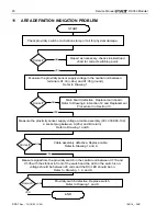
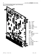
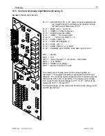
Measure voltage on the main board terminal strip between X1:31 (+9V±0.5) and
X1:2(ground). This is an input voltage from the system.
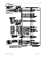
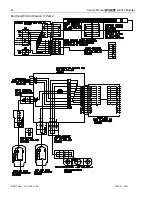
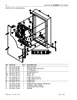
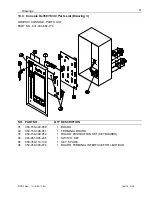
Refer to Drawing 1 and 4.
Correct?
Replace the main board in central unit.
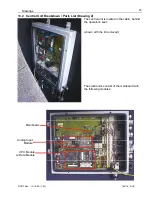
Refer to Drawing 2 and Replacement Procedure 2.
NO
YES
The A2B circuit supplies 9 volts to the circuit and a 4.7K resistor in the circuit modifies the return signal to
4.5 volts. The computer continuously monitors this signal to ensure the signal is between for a 3 to 6
volt, if the signal is:
!
less than 3 (open) A2B alarm and light. Check wiring for open circuit - switch not connected,
bypass plugs not installed, or sensor cables not connected
!
greater than 6 (short) then EAB error is given to the system. The signal is returned to the CU
unmodified; for example, a jumper wire connected between X1:31 and X1:32 in CU.
If the signal is within 3 to 6 volts or the A2B circuit is by-passed; LED H9 on the main board will be lit.
Refer to Drawing 3.
Measure voltage on the main board terminal strip between X1:31 (+9V±0.5) and
X1:32(A2B GND). This is the voltage in the A2B circuit. <3 open and >6 short in system
Refer to Drawing 1 and 4.
>6 volts
<3 volts
!
Look for damaged cable between central unit and boom tip
junction box.
!
Check 4.7K resistor in boom tip junction box. Turn system power
off and measure resistance between terminal 5 in junction box and
pin A of 7 socket receptacle. measurement reading = 4.7K .
!
check for short between terminals 5 and 6 in boom tip junction box
or between X1:31 and X1:32 in CU.
YES
YES
NEXT PAGE


