Service Manual
DS 350 Modular
© PAT
Rev. - 12/18/00 // CSH.
190118_-.DOC
18
10 LOAD
READING
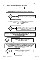
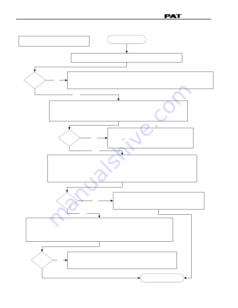
Measure radius and check with the displayed radius.
PROBLEM: Load reading incorrect.
START
Check if mechanical adjustment of angle transducer is correct. Angle transducer
box should be in line with boom and adjusted to actual boom angle.
Refer to Procedure 2: Angle Sensor Adjustment.
NEXT PAGE
NO
YES
YES
NO
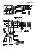
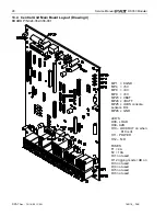
Measure the force transducer sensor supply voltage in the central unit
between terminals X1:23 (+12/24v) and X1:25 (ground).
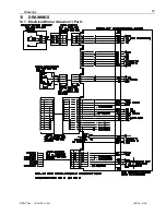
Refer to Drawing 1.
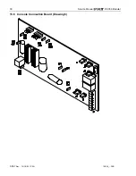
Main board defective. Replace main board.
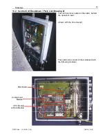
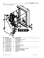
Refer to Drawing 2 in Section 12 and
Replacement Procedure 3 in Section 13.
NO
YES
Measure signals for main force transducer in the central unit.
measure voltage between X1:36 and X1:25 or amperage at X1:36.
voltage should be between 1.1..5.5 volt or amperage between 4..20mA.
Zero force on load cell equals 1.1V or 4mA. Refer to Drawing 1.
Correct?
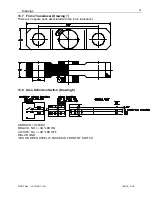
Fault in cable assemblies, cable reel, boom tip
junction box, and/or force transducer.
go to next page.
Correct?
Correct?
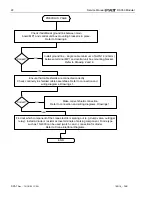
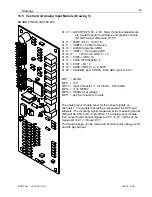
Measure signal from the force transducer on analog input board.
measure voltage between X1:7 and MP0.
voltage should be between 0.5..4.5 volts.
Zero force on load cell equals 0.5V. Refer to Drawing 2 and 5.
Analog Input board defective. Replace analog input board.
Refer to Drawing 2 and Procedure 2 steps 1, 2, 4, 11 12.
NO
Correct?


